Home / Solid fuel boilers
Back
Published: 04/25/2020
Reading time: 3 min
0
2575
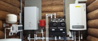
A brick boiler with a skeletal heat exchanger is a modern, improved modification of a brick stove, in which heating efficiency is increased by installing an internal heating circuit made in the form of pipe registers.
They are connected to a water heating system with standard heating appliances. Typically, such a heating source is installed in stove-heated houses or in large bathhouses.
The feasibility of installing this type of heating units depends on the smoke exhaust system and the availability of the room to accommodate a fairly large structure.
- 1 Why it is better to install tubular heat exchangers
- 2 Operating principle of a furnace with a built-in tubular heat exchanger
- 3 Pros and cons of a boiler with a skeletal heat exchanger
- 4 How to make a new furnace with water heating
Advantages and disadvantages
The mine unit has the following main advantages:
- Versatility, availability of work on different types of fuel, including liquid for modified installations.
- High boiler efficiency, productivity and autonomy without additional fuel loading up to 24 hours.
- A well-thought-out design that simplifies maintenance; loading/unloading is carried out through separate hatches.
- Reliability and safety, therefore, indoor gas pollution and carbon monoxide poisoning can be said to be reduced to “zero”.
The disadvantages include:
- increased soot and tar formation during fuel combustion;
- huge dimensions of the installation.
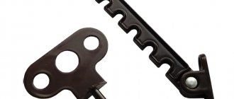
Installing a coil on a pipe
This is an excellent and fairly simple way to increase the efficiency of the stove. Flue gases heat the pipe to extremely high temperatures. The outer coil, like the inner one, helps reduce the temperature and somewhat cool the outer surfaces of the chimney. An external water heat exchanger is especially often installed on metal chimneys. This is an excellent auxiliary device for heating small spaces.
This heat exchanger has two pipes. The top one is connected to a pipe going to the storage tank, the bottom one is connected to the heating circuit. It is easy to make such a structure, as well as attach it to a pipe.
Use copper pipe or ready-made modules.
Features of the operation of mine boilers
The air enters under the grate and directly into the boiler through the ash door, which is why the fuel is burned. When this happens, flue gases are formed - they are discharged through the gas gap. The Kholmov boiler has such a design that the volume of air supplied through the blower door is initially no longer sufficient for complete combustion. As a result, a certain chemical burn is observed during operation of the device.
In our case, chemical underburning indicates that during oxidation, not pure carbon dioxide is formed, but the same, but in combination with carbon monoxide. The air that passes under the auxiliary grate is drawn into the holes on it. The number of these holes is such that the amount of secondary air is already too much. The heat intensity in this place is quite high and can reach 700-800 degrees, as a result of which the remaining carbon monoxide is oxidized.
After oxidation, the gas moves to the radiation compartment of the combustion chamber. There it is mixed, rises and is divided into a pair of streams thanks to the exchanger. Then, through the outlet pipe, the gas enters directly into the chimney. Convective thermal energy is absorbed by the exchanger and the walls located next to it. After passing through the inlet pipe, the working fluid, accordingly, hits the wall, after which it spreads and moves through the entire device between the heat exchanger and the chambers. The already heated coolant is supplied to the heating system through the outlet pipe at the top of the device.
Advantages
A boiler made of brick is considered a simple and effective heating structure, which is advisable to use for heating private houses. The advantage of such a structure is the possibility of making it yourself, which allows you to save a lot, as well as be confident in the quality of the materials used and the finished boiler. The manufacturing process itself consists of a minimum number of steps that do not require a large amount of welding work. Having purchased a ready-made heat exchanger, do not use welding. A brick boiler is multifunctional, as it can be used as a heating device for rooms. Additionally, as a hob for cooking.
In addition, such a boiler has the ability to maintain the required coolant temperature for a long time, allowing you to maintain a healthy and comfortable atmosphere in the room. A brick kiln allows you to burn even plastic or rubber waste. However, it is important to know that the firebox should not contain more than 1/3 of the total amount of fuel.
The process of making long-burning solid fuel boilers with your own hands: drawings and assembly
It should be noted right away that structures can have both an upper and a lower gas combustion chamber. In the first case, combustion products enter the working compartment under the influence of natural forces, and in the second, with the help of an additional device for pumping air.
Design drawings for self-production
Since boilers with a lower combustion chamber are difficult to manufacture and require the installation of additional equipment during installation, there is little point in considering them. It is faster and more economical to make a design with an upper chamber for burning gases.
An example of step-by-step production of a homemade unit
The following describes how to make a long-burning solid fuel boiler yourself, using available materials.
Applicable elements
To make the structure you will need:
- pipe with a cross-section of 500 mm and a length of 1300 mm;
- pipe with a diameter of 450 mm and a length of 1500 mm;
- pipe with a cross section of 60 mm and a length of 1200 mm;
- two rings 25 mm wide and 500 mm in diameter;
- metal corners and pieces of channel;
- Metal sheet;
- asbestos sheet;
- loops and handles.
The body of the structure can be made from such a pipe
Case assembly procedure
First of all, pipes with a cross-section of 1500 and 1300 mm are inserted into each other. They are connected using a ring made from a corner measuring 25x25 mm. A circle with a diameter of 450 mm is cut out of a metal sheet and fixed to the end of the pipe. It acts as the bottom. The result should be a small barrel.
A hole in the shape of a 15x10 cm rectangle is cut out from the bottom side of the structure for the ash pan door. The sash is attached to the opening using hinges, and a latch is also installed.
For the design, you can use a regular gas cylinder
A rectangular hole is made a little higher for the fuel chamber. The dimensions can be determined independently. The convenience of loading firewood or other fuel will depend on the correct dimensions. Using the same technology, a door with a latch is installed.
An outlet pipe is made in the upper part of the homemade structure, through which exhaust gases will flow into the chimney pipe. The pipes necessary for connection to the heating system of the building are fixed on the sides by welding. They must be threaded.
Location of the chimney pipe
Air distributor device
A circle is cut out of a piece of tin with a cross section 20-30 mm smaller than the diameter of the inner part of the boiler. A round hole is made in the central part for the air distribution pipe. Its diameter should be 6 cm. A pipe is inserted directly into the hole and welded to the base.
Air distributor with stabilizer
Pieces of corner are attached to the bottom of the metal pancake. On the other hand, a loop is fixed by welding, which is necessary to move the structure up and down. To adjust the air supply directly to the combustion chamber, a damper is installed.
Air distribution using welded corners
A circle with a diameter of 500 mm, cut from a suitable piece of metal, is inserted into the structure. The upper end of the pipe is inserted into the hole, after which the top cover of the boiler is welded tightly. A cable is attached to the loop, allowing the distributor to be lowered and raised.
View of the assembled structure
With pyrolysis combustion of solid fuel
A pyrolysis boiler is similar to a regular mine boiler, with a grate and the usual ignition of wood from below.
But it is characterized by the fact that the fuel does not burn in it, but smolders, releasing gas, which later burns separately (thanks to the supply of secondary air).
Such a unit has a water circuit both in the combustion chamber and in the afterburning chamber.
It is equipped with a draft sensor, dampers for adjusting the air supply and, in some models, a fan for pumping it up. A properly configured heating device has a high percentage of heat transfer.
A pyrolysis boiler requires dry fuel - ideally if the humidity is up to 10%.
Case manufacturing
The body is the main element of a wood-fired mine boiler.
It is made in the following sequence:
- First, they study the drawings of the future unit in order to determine the dimensions of all its metal elements.
- Rectangles are marked on sheet steel with lining, which will become the walls and parts of a homemade device.
- Sheets of metal are cut into blanks. This must be done using autogenous welding.
- Next, the side walls are welded.
- In the sheet from which the partition between the combustion and heat exchange compartments will be made, two holes are cut out - one at the top, the second slightly above the level of the grate. In this case, the height of the other hole should be 3 centimeters.
- The workpiece is placed inside the body, placed according to the drawing and welded. A valve is mounted on the upper hole on the side of the combustion chamber, welding its base. On the other side, attach a neck having a depth of 4 centimeters.
- To make a grate, narrow longitudinal holes are created in a piece of steel sheet with a lining. This item can be purchased ready-made. But it must be made of lined steel. A cast iron product will not be suitable, since after a few months of operation of the unit it will warp.
- Then the grate is welded.
- Holes are made in the side walls for the ash pan doors and for cleaning the afterburner chamber, along the perimeter of which the necks are welded so that they protrude outward and inward by 6 and 3 centimeters, respectively. It is advisable to attach the neck to the hole in the afterburning chamber after the heat exchanger has been fixed.
- 2 rows of metal corners or corrugated pipes are welded to the inner walls of the thermal chamber. The top row is placed at a distance of 3–4 centimeters from the top. The bottom row should be at the level of the bottom of the afterburning chamber. These rows will be part of the water jacket. It should be noted that it should not be done around the pyrolysis chamber, since as a result the entire process in it will be disrupted.
- The heat exchanger is welded to the inside of the water jacket.
- The bottom of the afterburning chamber must be welded at the level of the grate. In this case, one third of it is made horizontally located, and the rest is raised upward at an angle, the size of which depends on the drawing documentation. The area located near the internal partition should be horizontal.
- A hole is created above the bottom for a pipe supplying air.
- Many holes are drilled in a pipe with a cross-section of 5 centimeters. Next, it is welded to the hole in the body so that it protrudes outward by 6 centimeters. There should be no holes in this part. A valve is attached to the end of the pipe.
- The walls of the combustion chamber are lined with fireclay bricks, adjusting the materials to the required dimensions. Its top is made of brick protruding inward. A hole is installed between the bricks to move pyrolysis gases. Do the same with the afterburner chamber.
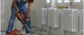
How to make a new furnace with water heating
There are many drawings on the Internet for making a heating stove with your own hands. If the developer lacks practical experience, it is safer to entrust such work to professionals who will carry it out, taking into account fire safety requirements and operating rules.
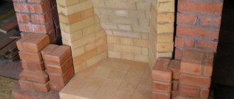
Algorithm for constructing a furnace with a skeletal heat exchanger:
- The heat exchanger is prepared according to the dimensions of the combustion chamber.
- A brick foundation is built for the stove, and waterproofed roofing felt is laid under the foundation.
- The bottom of the firebox and the ashpit are laid out with fireclay bricks, separated by a cast-iron grate.
- A skeletal heat exchanger is installed and a brick wall is laid out using a pattern. Ensure the size of the firebox so that there is a gap of up to 2 cm between them.
- A door is installed in front of the firebox.
- A channel for the smoke exhaust system is left behind the combustion chamber.
- A cast iron hob can be installed on top of the combustion chamber.
- The smoke exhaust duct is made of brick or steel pipe.
- Allow time for the masonry to dry thoroughly, then connect the in-house heating system to the heat exchanger pipes, which should contain a mud trap, shut-off and control valves, air vents, an expansion tank and radiators corresponding to the thermal load of the heated room.
- Finally, the heating system is pressure tested, a test fire is performed, and the performance of the heating equipment is checked.
When constructing a stove heating source, it is important to pay attention to the thickness of the walls, which are made of fire-resistant fireclay bricks. It depends on the type of fuel; for coal-fired devices, the walls are made wider.
This limitation should not be ignored, otherwise the stoves will burn out very quickly, and a new structure will have to be installed.
Making a classic model
Building a reliable TT boiler that can last more than 15 years requires the use of the following materials:
- low-carbon steel sheet grade St10-20, 4 mm thick, for the manufacture of a firebox;
- the same, 3 mm thick - for the water jacket and doors;
- metal strip with a cross section of 20 x 3 or 20 x 4 mm;
- a piece of pipe with a diameter of 150 mm for the chimney;
- pipe Ø57 mm with a wall thickness of at least 3.5 mm for the heat exchanger;
- profile pipe 6 x 4 cm for the air duct;
- a corner with a shelf width of 5 cm made of thick metal (4-5 mm) on a grate;
- thin sheet steel with powder painting for external cladding.
Additional materials will require basalt fiber with a density of 80-100 kg/m³ for thermal insulation of the body and asbestos-graphite cord for sealing the door ledges. The automation kit and fan, which were mentioned in the previous section, are made in Poland, model KG Elektronik SP-05. There are also Chinese analogues on the market, they are cheaper.
Step one - welding the body
To weld the fuel chamber, it is necessary to cut 4 mm metal into blanks according to the dimensions indicated in the drawing. Start assembling from the bottom of the ash pan - grab the side walls and lid to it, and then form frames for the loading and cleaning door, as done in the photo.
Then follow this algorithm:
- Weld supports for the grate inside the firebox, and weld clips from a steel strip outside for mounting the water jacket.
- Install and weld the 3mm outer lining sheets of the water jacket. Note that it originates from the top of the ash chamber.
- In the upper compartment, which will subsequently be filled with coolant, cut 4 flame pipes Ø50 mm, and place the same pipes for connection to the heating system.
- Attach legs from pieces of any rolled metal to the unit and install a chimney pipe at the outlet of the fire tube heat exchanger.
Please note that the flame tubes converge in a bundle towards the chimney pipe
Stage two - installation of hanging elements
The doors of the fuel and ash chamber are made by bending the edges of the blanks and welding the internal frame, where the basalt insulation is laid. The insulation is hermetically sealed on top with a lid, and an asbestos-graphite cord is tightly inserted into the resulting groove along the perimeter of the sash.
What else needs to be done:
- Attach the handles and hinges to the body, and cover the doors with heat-resistant enamel.
- Weld a grate from the corners and put it in place.
- Make an air duct with a counter flange and weld it to the rear wall, as shown in the photo.
To insulate and line a homemade TT boiler, it is necessary to weld embedded parts made of any metal at the corners of the water jacket, as long as its width does not exceed 20 mm (on the back wall - 4 cm). Also provide stands for mounting the ECU on the top of the unit.
Final assembly of the heater
Thermal insulation of the boiler tank is simple - the walls are lined on the outside with basalt wool slabs, which are secured with a cord. Make sure that the insulation fits tightly to the frame of the loading and ash opening, as well as to the profile pipe of the air duct.
This is how the control unit and fan are mounted
The last step is to cover the heat generator with polymer-painted metal, screwed with self-tapping screws to previously welded embedded parts. After this, the doors are hung and an automation unit with a fan is installed. An original video from the developer of this long-burning TT boiler, Vitaly Dashko, will help you understand the assembly process:
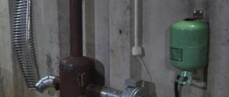
Installing a water circuit in the chimney
The water circuit heat exchanger has a complex design. One of the options for its placement is to be built into the chimney. The furnace can be initially built with a coil, or it can be built into a ready-made structure.
Peculiarities
This method allows you to use heat, which quickly and practically uselessly flies into the pipe. Wherein:
- The decision to install this type of circuit is made at the furnace design stage. It is virtually impossible to integrate a heat exchanger into the chimney of a stove that has already been put into operation.
- Heat is not taken away from the stove; the firebox heats up to the maximum.
- The degree of heating of the coolant is regulated by the length of the coil. For a large house - a large coil.
- The service life of the coil built into the smoke duct is much longer, since there is no contact with fire.
- Requires a stove with a rather large and complex chimney, which leads to an increase in the size of the stove.
Why do buyers choose Teplodar stoves?
durable heat-resistant glass
The use of modern technological methods in the design of heating equipment leads to elegant lines and perfect fit of parts, completely eliminating the possibility of defects. High-quality products are produced only through the use of the most modern equipment.
The stoves differ from analogues presented by other manufacturers of heating equipment in their beautiful modern appearance and ease of operation. An important fact is that any model for the Teplodar house is characterized by high fire safety
This is very important, since the likelihood of a fire when using heating equipment of this kind is always present. Ease of installation and compactness are also big advantages of this product.
And probably one of the main advantages of heating equipment on the market is its relatively low price. Unlike foreign analogues, the domestic one provides not very expensive products that are of very high quality. This is one of the main reasons for the attractiveness of this company’s heating equipment for a huge number of buyers interested in Teplodar brand products.
Covering instructions
Step-by-step instructions on how to line an iron stove with bricks in a bathhouse or house are as follows:
- First, a cord protruding as a level is pulled. As it is laid, it is raised higher;
- Then the first and second layers are laid out, which are coated with the solution. The width of the seams between layers should be up to seven millimeters, and horizontal ones up to ten. It is very important that the first row is executed perfectly, since it is fundamental for the others.
- Next, small ventilation gaps are created, and the masonry continues according to the pattern previously selected for the formation of the stove;
- By the third row, excess mortar is removed using a rubber hammer or trowel;
- The masonry continues to the level of the slab or to the ceiling, covering the chimney.
At the time of laying, it is important to understand that when the master reaches the ash pit and firebox, it is necessary to correctly position the window with hinges. When installing near doors, you need to check the ease of operation.
Note! The laid wall should not prevent the doors from opening freely. It is also necessary to make several holes near the chimney responsible for ventilation.
Common mistakes
The brick chimney is crumbling due to the formation of condensation. When installing the channel, mistakes are made that contribute to the accelerated formation of moisture and reduce the service life of the structure:
- Insufficient pipe height. A thick layer of adhering soot due to untimely cleaning of the channel and incorrect dimensions of the air duct provokes weak draft.
- The presence of uninsulated areas of the chimney (for example, an attic).
- Incorrect connection between the gas boiler and the duct. The splicing should be carried out with a stainless pipe or corrugated pipe, extending it at least 0.5 m vertically into the brick well, the horizontal section should not exceed 1 m.
Tip 2: arranging the base and marking the contours of the masonry
Foundation diagram for a metal furnace.
Before covering a metal stove with bricks, you should make sure that the floor surface will not bend and will support the weight of the cladding and mortar. Of course, if the base for the masonry is made of concrete or finished with durable ceramic tiles, it will not be deformed and no additional work on arranging the floor will be required. When there is no complete confidence in the stability of the foundation to the load, a separate foundation is made for the masonry area or additional supports are placed under the load-bearing floor beams.
At the preliminary stage, the contours of the future masonry are also marked. To do this, step back a distance of 1 to 10 cm from the stove and outline the location of future brick rows with precise drawing of right angles. When choosing a gap between the stove and the brick, you need to take into account that the smaller the distance between the masonry and the metal surface, the greater the overheating of the stove walls. If the gap is too large, heating of the brick will be very slow.
Figure 2. Laying rows of refractory bricks.
According to experts, the optimal distance between the stove and the brick, at which the room is heated quite quickly without overheating the metal of the stove walls, is within 3-5 cm. This should be adhered to.
After applying the markings, a metal sheet 2-4 mm thick is attached to the floor of a size that would overlap the contours of the future masonry. And on top of it they lay asbestos cardboard with a sheet thickness of up to 1 cm. Now you can proceed directly to the cladding.
Return to contents
If a metal sauna stove lined with brick is not suitable for installation according to the table, then in this case it is necessary to make a foundation. This task is simplified if you have just started building a building with your own hands and you do not need to dismantle the stove and floors.
To build a foundation, a hole about half a meter deep is dug around the perimeter of the masonry and filled 3/5 with crushed stone or a mixture of gravel and sand. It must be taken into account that contact with the bathhouse foundation is unacceptable.
After laying the cushion, a cement screed and a layer of waterproofing are made, after which formwork is made, which is filled with concrete mortar. For such a product to harden properly, it must be regularly moistened with water to avoid cracks.
Important information
Advanced industrial models, despite their high cost, allow for significant savings during their long-term operation due to lower fuel consumption and the need for frequent maintenance.
It is almost impossible to make a high-tech heating device at home that has all the qualities of industrial analogues. In this regard, most homemade boilers have a fairly simple design made from cheap materials. They, as a rule, have low efficiency, require frequent maintenance (cleaning of ash and soot) and constant supervision during operation.
When deciding to independently manufacture a solid fuel boiler, you need to realistically assess your technical skills and abilities, the availability of the necessary materials and tools, as well as the approximate costs of purchasing them.
During work (especially when using welding), all fire safety measures should be carefully followed.
Description of equipment
Long-burning mine boilers are an effective technology that is characterized by the longest possible fuel burning time and unique design features. The presence of a fuel chamber with increased dimensions eliminates the need for frequent loading, and thanks to the special design of the blower, slow combustion is ensured with the release of a large amount of heat.
The most widespread today are two designs of mine boilers:
- Pyrolysis.
- With normal combustion.
Both of these designs have two chambers, one of which contains a heat exchanger, and the second is used for burning fuel. The shaft-type boiler with bottom combustion is characterized by a simple design and has a firebox as high as the entire unit, which makes loading significantly easier. The combustion chamber resembles a shaft in appearance, which served as the name for heating equipment of this type.
In this video we will look at a mine boiler:
The heat exchanger chamber is made using classic fire tube technology. Inside this compartment there are numerous pipes through which a heat exchanger circulates, heated by hot air coming from the firebox. The chimney can be made either in the form of a vertical pipe or a coaxial type, which is discharged through the nearest wall to the street.
Mine boilers for long-term bottom burning with wood received a modified design, which made it possible to ensure the longest possible combustion. This boiler is supplemented with the following elements:
- In additional chambers located under the heat exchanger, carbon monoxide is burned, which improves the efficiency of the boiler.
- Pipes with numerous small holes are installed in the pyrolysis chamber, which allows the supply of air necessary for the combustion of carbon monoxide.
- Directly above the pyrolysis chamber there is a valve, which allows you to reduce and increase the intensity of fuel combustion.
Final stage
The following work needs to be done:
- The top of the inner part of the water jacket is secured by welding.
- A hole is drilled in it for the chimney and a 130 mm pipe is welded.
- A similar hole is created in the upper part of the unit body and the workpiece is secured.
- Holes are drilled at the top and bottom of the water jacket, after which pipes made from 25 mm tubes are welded.
- To check the tightness of the heat exchanger, it is filled with water and the pressure is raised.
- The bottom is attached to the structure.
- A corrugated pipe measuring 20x20 millimeters is welded on all sides along the perimeter.
- A steel sheet 1-2 millimeters thick is attached to the top.
- The doors are fixed - combustion and loading.
- The structure is completely sheathed with basalt wool and then with galvanized sheets.
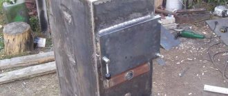
You can also build a mine boiler from brick. Its structural design is different in that firewood is loaded into it through a hatch into a high loading chamber, hence the name of the unit.
Mechanism of operation
There are various types of solid fuel boilers and heat exchangers for them, which can be designed independently. Vertical and horizontal brick structures are popular. They work as follows:
- By burning fuel, the air is heated and, rising, is discharged through the chimney.
- When moving, the heated air transfers heat to the heat exchanger, which, in turn, heats the water.
- H2O circulation occurs (cold water is replaced by hot water).
There is another type of heating device - a brick mine boiler, the distinctive feature of which is the loading of fuel through a special hatch. For its construction, rectangular heat exchangers are used, which are made of sheet metal, equipped with several rows of vertical pipes that pass flame and heated gas through them. This type of boiler allows you to change the combustion duration by adjusting the height of the loading area (shaft) and air supply.