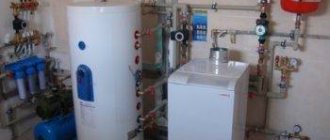
If you think that only a specialist with a technical background can understand the design of a hydraulic arrow, then you are mistaken. In this article we will explain in an accessible form the purpose
basic principles of its functioning and rational calculation methods.
Hydroarrow
(synonyms: hydrodynamic thermal separator, hydraulic separator, and in Russian - anuloid) is a device designed to equalize both temperature and pressure in the heating system. To put it simply, we reset the pressure in the supply and the pressure in the brother.
Main functions
- increasing energy efficiency by increasing the efficiency of the boiler and pumps, which leads to lower fuel costs;
- ensuring stable operation of the system;
- eliminating the hydrodynamic impact of some circuits on the total energy balance of the entire heating system (to separate the radiator heating circuit and the heating boiler).
What forms of hydraulic arrow exist?
A hydrodynamic thermal separator is a vertical volumetric container, which in cross section can be in the form of a circle or square
Taking into account the theory of hydraulics, a round-shaped hydraulic needle functions better than its square-shaped counterpart.
Nevertheless, the second option fits optimally into the interior. Before studying the principle of operation of the hydraulic arrow
, pay attention to the diagram below.
Pumps Gp and Gs create flow in the first and second circuits, respectively. Thanks to the operation of the pumps, the coolant circulates in the circuits and mixes it in the hydraulic arrow.
Option 1. If Gp = Gs the coolant moves from one circuit to the second, then the temperature in the primary and secondary circuits is the same.
Option 2. If Gp > Gs, the coolant moves in the hydraulic arrow from top to bottom, and the temperature in the supply circuit will be the same in both the primary and secondary circuits.
Option 3. If Gp < Gs the coolant moves from bottom to top in the hydraulic switch, now the return line temperature is the same in both the primary and secondary circuits.
Based on the above, it follows that the Hydroarrow must be selected according to the maximum flow rate in any of the heating circuits.
Thus, a hydrodynamic thermal separator is needed when there is a heating system that is complex in design, consisting of many circuits.
A little about the numbers...
There are several methods by which the hydraulic arrow is calculated.
The diameter of the hydraulic separator is determined by the following formula:
Where D is the diameter of the hydraulic needle, Q is the water flow rate (m3/s), π is a constant equal to 3.14, and V is the vertical flow velocity (m/s). It should be noted that the economically advantageous speed is 0.1 m/s.
The numerical values of the diameters of the nozzles included in the hydraulic arrow are also calculated using the above formula. The difference is that the speed in this case is 0.7-1.2 m/s, and the flow rate (Q) is calculated for each carrier separately.
The volume of the hydraulic arrow affects the quality of the system’s functioning and helps regulate temperature fluctuations. The effective volume of a heating system with a hydraulic arrow is 100-300 liters.
To determine the optimal dimensions of a hydrodynamic thermal separator, the method of three diameters and alternating pipes is used.
We calculate using the formula:
Where π is a constant equal to 3.14, P is the boiler power (in J), C is the heat capacity of the coolant (for water 4.183 kJ/(kg•°C), W is the speed at which the coolant moves in the hydraulic arrow (m/s ), ΔT is the temperature difference between the heat supply points from the boiler (upper and lower).
( 3 • d ) - indicator calculated by trial and error.
| Boiler power | D pipes from the boiler | D pipe under the arrow |
| 70 kW | 32 | 100 |
| 40 kW | 25 | 80 |
| 26 kW | 20 | 65 |
| 15 kW | 15 | 50 |
Only pros and no cons
Based on the above, the following advantages of using hydraulic arrows can be identified:
- optimization of operation and increase in the service life of boiler equipment;
- system stability;
- simplification of pump ;
- the ability to control the temperature gradient;
- if necessary, you can change the temperature in any of the circuits;
- ease of use;
- high economic efficiency.
In order not to worry about the uninterrupted operation of the heating system, to minimize heat loss, to increase the efficiency of the boiler, and to maintain the temperature in the entire house at the most comfortable and stable level, a hydraulic arrow is needed.
This container stabilizes the distribution of coolant over the entire area of the room, extending the life of the heating system, as it prevents the occurrence of water hammer.
Why do they trust us with the calculation and installation of hydraulic arrows?
You should not install the hydraulic arrow yourself. It’s better to contact our organization because:
- We have experienced design engineers on our staff who will correctly perform all calculations;
- our installation technicians will competently carry out all installation work;
- We will carry out not only commissioning work, but also provide subsequent maintenance;
- People trust us because we do everything with high quality and for many years.
The use of hydraulic arrows with solid fuel equipment
When using a solid fuel unit, the hydraulic separator is connected at the inlet-outlet point.
This option for connecting different types of heating devices ensures the selection of optimal and individual temperature conditions for all components separately. Today, consumers, having understood how a hydraulic heating device works, prefer ready-made products that are on sale. Select a hydraulic separator from the catalog, based on the power of the unit and the maximum water flow.
Cavitation
Cavitation is the formation of vapor bubbles in the thickness of a moving liquid when the hydrostatic pressure decreases and the collapse of these bubbles in the thickness where the hydrostatic pressure increases.
In centrifugal pumps, cavitation occurs at the leading edge of the impeller, the location with maximum flow velocity and minimum hydrostatic pressure. The collapse of a vapor bubble occurs during its complete condensation, and at the point of collapse there is a sharp increase in pressure up to hundreds of atmospheres. If at the moment of collapse the bubble was on the surface of the impeller or blade, then the impact falls on this surface, which causes metal erosion. The metal surface subject to cavitation erosion is chipped.
Cavitation in the pump is accompanied by sharp noise, crackling, vibration and, most importantly, a drop in pressure, power, flow and efficiency. There are no materials that are absolutely resistant to cavitation destruction, so operating the pump in cavitation mode is not allowed. The minimum pressure at the inlet to a centrifugal pump is called NPSH and is indicated by pump manufacturers in the technical description
The minimum pressure at the inlet to a centrifugal pump is called NPSH and is indicated by pump manufacturers in the technical description.
DIY thermal separator
The design of the hydraulic arrow is so simple that it allows the owner of a country house to assemble it himself without much difficulty. An important manufacturing stage is the correct calculation of the diameters of the nozzles and separator. The simple design of the unit follows the rule of 3 diameters.
It is possible to make a hydraulic arrow yourself
In this case, the diameter of the pipe is taken as a basis, which is the same for all inlet and outlet circuits. The total diameter of the hydraulic arrow will be equal to 3 diameters of the pipe, and its length should be 4 diameters of the separator. The axes of the inlet and outlet pipelines will be located from the ends of the structure at a distance of one diameter of the thermal separator.
This size ratio allows you to reduce the speed of movement of the coolant to the desired results. In the future, you just need to select pipes of suitable sizes and carry out welding work. This simple design will work successfully in small heating systems.
Operating principle of the hydraulic boom:
Grundfos pump models
UPS pumps are circulation type units with a wet rotor. These models use an asynchronous motor. The pump is equipped with a special terminal box, which ensures the connection of the unit to electricity. During initial start-up, it is recommended to open the technological opening and bleed air from the working chamber of the pump. The design also provides for the possibility of manually turning the rotor in case of souring. These pumps have three speed modes of operation, which are set manually and ensure stable operation of certain systems.
The new model AIpha 2 (L) pumps are the first in the general line of the series. This pump has more capabilities than the UPS series pumps. There is an electric motor here that has permanent magnets on the body. If one of the magnets is removed, which Russian craftsmen do in many cases, the energy consumption of the unit can be significantly reduced. Also in the new design there is no technological nut for air release. In this model, air is automatically released when the pump is turned on briefly at third speed. Connecting to the power supply has become easier, this is done using a plug connector. This model already has seven operating modes. To the existing three, two more operating modes with a constant differential pressure and two proportional control modes have been added.
Pump operation in constant differential mode - assumes stable operation of the pump even in cases where changes in fluid flow and pressure drop occur in the system. A certain level of pressure created by the pump will always be automatically maintained at the same level.
Proportional control mode - this operating mode ensures reliable operation of the pump when the system experiences variable flow. This mode cannot be replaced if during operation the radiators periodically overlap, which leads to an increase in pressure in the system. The pump rotation speed is automatically reduced, as a result, the flow and pressure in the system will decrease proportionally. There are still three main modes of operation. Systems in which they are used;
- warm floor,
- single pipe systems,
- dead-end systems,
- collector systems,
- two-pipe systems,
- radiator systems.
The most innovative can be called the AIpha 3 model. This model can be considered as a very precise tool that is capable of simultaneously ensuring reliable operation of the entire system and at the same time allows you to control coolant flow. This feature can be used in conjunction with the Grundfos GO Balance app. The presence of these applications allows you to configure the entire fuel system remotely. This equipment can also be used to measure and balance the entire heating system, installing it in place of another circulation pump that is suitable in size and dimensions. The pump is especially good for balancing radiators, short loops in a heated floor system, as well as for low coolant flows. The possibility of three-fold gradation of both constant and proportional pressure modes makes this model very reliable and productive. After all, as you know, for any master installing a heating system, the ability of the installed equipment to ensure normal coolant flow is very important, and for the customer, the reliability and efficiency of this system is important. The circulation pump gives a positive result to both. Economical and quite easy to maintain, this pump is very well suited for installing autonomous heating in country houses and individual apartments.
What should you know?
The hydraulic arrow is an additional unit, which is located in a vertical position. It is made in the form of a cylinder, but can also have a cross-section in the form of a rectangle. This device is fitted with pipes that connect to the boiler, as well as to the heat exchange circuits. This device divides a small circuit, as well as extended heating circuits. Traditional hydraulic divider designs are often used.
Device diagram
Such a device maintains temperature and hydraulic balance. With its help, you can achieve small pressure losses, as well as thermal energy and productivity. The design allows you to increase the efficiency of the heating system and reduce resistance in the system.
Important characteristics include the diameters of the pipes and the main device. The remaining parameters can be found in the standard diagrams.
Built-in hydraulic catcher
The program has some nuances:
When calculating, the power of the heating equipment must be used
To determine this indicator, you can also use a special calculation program; An important characteristic is the speed of movement of the coolant in the vertical direction. The lower this indicator, the better the coolant will get rid of gases and sludge
Also in this case, there will be a smoother mixing of the cooled and hot flows. The best option is 0.1-0.2 m/s. In the program you can select the required parameter; A special characteristic is the operating mode of the entire structure. In this case, the temperature levels in the line passing from the heating device are taken into account. All indicators are entered into the calculator.
A special calculation formula is provided in the applied calculation algorithm. As a result, a result will be shown that will show the suitable diameter for the hydraulic arrow, as well as the cross-section of the pipes used. The remaining parameters of the linear type are even easier to determine.
Before you begin installing such a device, it is worth studying all the functions of the hydraulic arrow.
Related article:
Save time: selected articles delivered to your inbox every week
What is a hydraulic needle really needed for - debunking the myths
Having examined the technical side of the hydraulic separator, let’s move on to the issue of its operation. So why do you need a hydraulic arrow in a heating system?
First, let's look at what properties are often attributed to this element:
- increasing the stability of the system;
- increasing boiler efficiency;
- reduction of fuel costs;
- ensuring stability of coolant movement;
- increasing the operating life of the heating device.
These advantages, although they sound nice, are mostly not true. The only point worthy of attention is “increasing the life of the heating device.” As noted above, the hydraulic separator in the heating system is able to protect the boiler from thermal shock by heating the return flow of coolant. However, a regular bypass installed at the outlet of the device between the supply and return can cope with this task.
To protect the boiler from thermal shock, it is easier to install a bypass instead of a hydraulic arrow
Despite the fact that the hydraulic arrow is assigned many functions, it is needed to solve only one task - to ensure optimal operation of pumping equipment installed in different heating circuits.
If the system uses several pumps with different capacities, then the most powerful of them will create a large vacuum in the supply pipeline and excess pressure in the return line. Thus, a poorly performing pump will not be able to provide its own circuit with a sufficient amount of coolant. To avoid such a situation, a hydraulic arrow is installed - a section with zero resistance. Thanks to this element, the pressure difference between forward and reverse supply is equalized, and all pumps can operate in optimal mode.
A hydraulic separator is needed to coordinate the operation of several heating circuits
Popular manufacturers
There are not as few companies involved in the production of hydraulic separators for heating networks as it might seem at first glance. However, today we will get acquainted with the products of only two companies, GIDRUSS and Atom LLC, since they are considered the most popular.
Table. Characteristics of hydraulic separators manufactured by GIDRUSS.
| Model, illustration | Main characteristics |
| 1. GR-40-20 | — the product is made of structural steel; — designed for one consumer; — minimum power of the heating device is 1 kilowatt; — its maximum power is 40 kilowatts. |
| 2. GR-60-25 | — the product is made of structural steel; — designed for one consumer; — the minimum power of the heating device is 10 kilowatts; — its maximum power is 60 kilowatts. |
| 3. GR-100-32 | — the product is made of structural steel; — designed for one consumer; — minimum power of the heating device is 41 kilowatts; — its maximum power is 100 kilowatts. |
| 4. GR-150-40 | — the product is made of structural steel; — designed for one consumer; — minimum power of the heating device is 61 kilowatts; — its maximum power is 150 kilowatts. |
| 5. GR-250-50 | — the product is made of structural steel; — designed for one consumer; — the minimum power of the heating device is 101 kilowatts; — its maximum power is 250 kilowatts. |
| 6. GR-300-65 | — the product is made of structural steel; — designed for one consumer; — minimum power of the heating device is 151 kilowatts; — its maximum power is 300 kilowatts. |
| 7. GR-400-65 | — the product is made of structural steel; — designed for one consumer; — minimum power of the heating device is 151 kilowatts; — its maximum power is 400 kilowatts. |
| 8. GR-600-80 | — the product is made of structural steel; — designed for one consumer; — minimum power of the heating device is 251 kilowatts; — its maximum power is 600 kilowatts. |
| 9. GR-1000-100 | — the product is made of structural steel; — designed for one consumer; — minimum power of the heating device is 401 kilowatts; — its maximum power is 1000 kilowatts. |
| 10.GR-2000-150 | — the product is made of structural steel; — designed for one consumer; — minimum power of the heating device is 601 kilowatts; — its maximum power is 2000 kilowatts. |
| 11. GRSS-40-20 | — the product is made of AISI 304 stainless steel; — designed for one consumer; — minimum power of the heating device is 1 kilowatt; — its maximum power is 40 kilowatts. |
| 12. GRSS-60-25 | — the product is made of AISI 304 stainless steel; — designed for one consumer; — the minimum power of the heating device is 11 kilowatts; — its maximum power is 60 kilowatts. |
| 13. GRSS-100-32 | — the product is made of AISI 304 stainless steel; — designed for one consumer; — minimum power of the heating device is 41 kilowatts; — its maximum power is 100 kilowatts. |
Let us also note that each hydraulic arrow for heating listed above also performs the functions of a kind of sump. The working fluid in these devices is cleared of various types of mechanical impurities, which significantly increases the service life of all moving components of the heating system.
Is it possible to install one pump per circuit?
It would seem quite logical to equip each heating circuit with its own circulation pump that meets all the necessary parameters in order to solve the problem. Is it so? Unfortunately, even in this case the problem will not be solved - it will simply move to another level! Indeed, for the stable functioning of such a system, an accurate calculation of each pump is necessary, but even with this, a complex multi-circuit system will not become equilibrium. Each pump here will be associated with its own circuit, and its characteristics will change (that is, they will not be stable). In this case, one of the circuits can fully operate, and the second can be turned off. Due to circulation in one circuit, inertial movement of the working fluid may occur in an adjacent circuit, where this is not required at all (at least for the moment). And there can be a lot of such examples.
As a result, the underfloor heating system may overheat unacceptably, different rooms may be heated unevenly, and individual circuits may become “locked up.” In a word, everything is happening to ensure that your efforts to equip the system with high efficiency go down the drain.
Note! This especially affects the pump installed next to the heating boiler. And in many homes, several heating devices are used at once, which are extremely difficult, almost impossible, to control. Because of all this, expensive equipment simply fails.
Is there a way out? Yes - not only divide the network into circuits, but also take care of a separate circuit for the heating boiler. And we’ll help you with balancing the hydraulic valve for heating, or, as it is also called, the hydraulic separator.
The role of the hydraulic arrow in modern heating systems
In order to find out what a hydraulic arrow is and what functions it performs, first we will get acquainted with the features of the operation of individual heating systems.
Simple option
The simplest version of a heating system equipped with a circulation pump will look something like this.
Of course, this diagram is significantly simplified, since many network elements in it (for example, the security group) are simply not shown in order to “make the picture easier to understand.” So, in the diagram you can see, first of all, a heating boiler, thanks to which the working fluid is heated. Also visible is a circulation pump, through which the liquid moves through the supply (red) pipeline and the so-called “return”. Typically, such a pump can be installed both in the pipeline and directly in the boiler (the latter option is more typical for wall-mounted devices).
Note! There are also heating radiators in the closed circuit, thanks to which heat exchange occurs, that is, the generated heat is transferred to the room. If the pump is correctly selected in terms of pressure and performance, then it alone will be quite sufficient for a single-circuit system, therefore, there is no need to use other auxiliary devices
If the pump is correctly selected in terms of pressure and performance, then it alone will be quite sufficient for a single-circuit system, therefore, there is no need to use other auxiliary devices.
More complex option
If the area of the house is large enough, then the diagram presented above will clearly not be enough for it. In such cases, several heating circuits are used at once, so the diagram will look slightly different.
Here we see that through the pump, the working fluid enters the manifold, and from there it is transferred to several heating circuits. The latter include the following elements.
- A high temperature circuit (or several), in which there are collectors or ordinary batteries.
- DHW systems equipped with an indirect heating boiler. The requirements for the movement of working fluid are special here, since the temperature of water heating in most cases is regulated by changing the flow rate of the fluid passing through the boiler.
- Warm floor. Yes, the temperature of the working fluid for them should be an order of magnitude lower, which is why special thermostatic devices are used. Moreover, the contours of the heated floor have a length significantly exceeding the standard wiring.
It is quite obvious that one circulation pump cannot cope with this kind of load. Of course, today high-performance models with increased power are sold, capable of creating quite high pressure, but it is worth thinking about the heating device itself - its capabilities, alas, are not limitless. The fact is that the boiler elements are initially designed for certain pressure and performance indicators. And these indicators should not be exceeded, as this can lead to breakdown of the expensive heating installation.
In addition, the circulation pump itself, operating at the limit of its capabilities in order to supply all circuits of the network with liquid, will not be able to last long. What can we say about the loud noise and electrical energy consumption. But let's return to the topic of our article - to the hydraulic arrow for heating.
Which circulation pump to choose?
In addition to the main characteristics, it is necessary to pay attention to other indicators of this device:
Scheme for selecting a pump for a heating system.
Economical. A very important factor, and it will depend on the type of pump, design features, and the presence of an electronic control unit. It will save up to 40% of electrical energy and extend the service life of the pump. This device controls the rotation speed of the rotor depending on the need for heating intensity. Since the device will not always operate at full power, the noise level created by it will be significantly reduced. Margin of safety. After calculating the pressure and pump output required for your fuel system, add another 10-20% to these figures. Thus, the device you installed will not wear out, but will use its resource optimally. The service life of modern pumps depends on the quality of their performance. If installed and used correctly, they last about 10 years. To achieve this, install the devices before entering the heating boiler. At this point in the system, the coolant temperature is lowest, and the wear of pump parts in contact with water is not as severe. For ease of dismantling the unit and its subsequent maintenance, shut-off valves are installed before and after the pump installation site. If the system has a membrane-type expansion tank, then the pump is installed behind it, in the direction of flow of the coolant. This connection point allows for the most efficient removal of air. Remember that the formation of air pockets is unacceptable. When installing the circulation unit, it is necessary to position it so that the axis of rotation of the shaft is in a horizontal plane
You should pay attention to the degree of contamination of the working fluid. A large amount of abrasive substances that may be in the water will not add to the service life of the pump.
Why do you need a hydraulic arrow: principle of operation, purpose and calculations
Many heating systems in private households are unbalanced. The hydraulic arrow allows you to separate the circuit of the heating unit and the secondary circuit of the heating system. This improves the quality and reliability of the system.
Features of the device
When choosing a hydraulic gun, you need to carefully study the principle of operation, purpose and calculations, and also find out the advantages of the device:
- the separator is necessary to ensure that the technical specifications are met;
- the device maintains temperature and hydraulic balance;
- parallel connection ensures minimal losses of thermal energy, productivity and pressure;
- protects the boiler from thermal shock and also equalizes circulation in the circuits;
- allows you to save fuel and electricity;
- a constant volume of water is maintained;
- reduces hydraulic resistance.
Operation of the device with a four-way mixer
The operating features of the hydraulic switch make it possible to normalize hydrodynamic processes in the system.
Helpful information! Timely removal of impurities allows you to extend the service life of meters, heating devices and valves.
Hydraulic heating device
Before you buy a hydraulic arrow for heating, you need to understand the structure of the structure.
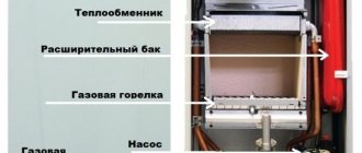
Internal structure of modern equipment
The hydraulic separator is a vertical vessel made of large diameter pipes with special plugs at the ends. The dimensions of the structure depend on the length and volume of the circuits, as well as on the power. In this case, the metal case is installed on support posts, and small-sized products are mounted on brackets.
Connection to the heating pipeline is made using threads and flanges. The material used for the hydraulic arrow is stainless steel, copper or polypropylene. In this case, the body is treated with an anti-corrosion substance.
Note! Polymer products are used in a system with a boiler with a capacity of 14-35 kW. Making such a device with your own hands requires professional skills.
Additional equipment functions
The principle of operation, purpose and calculations of the hydraulic arrow can be learned and performed independently. The new models have the functions of a separator, separator and temperature regulator. A temperature control valve provides a temperature gradient for the secondary circuits. Removing oxygen from the coolant reduces the risk of erosion of the internal surfaces of equipment. Removing excess particles increases impeller life.
Inside the device there are perforated partitions that divide the internal volume in half. This does not create additional resistance.
The diagram shows a sectional view of the device
Helpful information! Complex equipment requires a temperature sensor, a pressure gauge and a line to power the system.
The principle of operation of a hydraulic arrow in heating systems
The choice of hydraulic arrow depends on the speed of the coolant. In this case, the buffer zone separates the heating circuit and the heating boiler.
There are the following hydraulic arrow connection diagrams:
neutral operating scheme, in which all parameters correspond to the calculated values. At the same time, the design has sufficient total power;
Using a heated floor circuit
a certain scheme is used if the boiler does not have sufficient power. If there is insufficient flow, an admixture of cooled coolant is required. When there is a temperature difference, thermal sensors are triggered;
Heating system diagram
the flow volume in the primary circuit is greater than the coolant consumption in the secondary circuit. In this case, the heating unit operates in optimal mode. When the pumps in the second circuit are turned off, the coolant moves through the hydraulic valve along the first circuit.
Option for using a hydraulic arrow
The performance of the circulation pump should be 10% greater than the pressure of the pumps in the secondary circuit.
Features of the system
This table shows some models and their prices.
The nuances of installing a hydraulic arrow for heating systems
The usual, generally accepted arrangement of such equipment is vertical. This allows the device to settle heavy particles and prevent them from reaching the pump, which increases its service life. In the upper part of the tank, excess air from the coolant collects, the entry of which into metal lines increases the rate of their corrosion.
One of a kind. Model VALTEC VT.VAR00.G
If we talk about a heating system made entirely of polypropylene, then it is devoid of such problems, which means that the hydraulic separator can be chosen of any type - both vertical and horizontal.
To save space, some craftsmen even place hand-made hydraulic arrows diagonally. This is quite acceptable, but it should be understood that the outlet pipes will have to be positioned differently in this case. Otherwise, such a product will not perform its function or will have large errors.
The dimensions of the hydraulic arrow depend on the power of the boiler and the characteristics of the circulation pumps
Calculation method
To make a hydraulic arrow for heating with your own hands, you will need preliminary calculations. This figure shows the principle by which the dimensions of a device can be calculated quickly, with fairly high accuracy.
"3d" principle
These proportions were obtained taking into account the results of experiments and the efficiency of the device in different modes. The value of D, which consists of three d, can be calculated using the following formula:
- РВ – water consumption in cubic meters;
- SP – water flow speed in m/s.
In order to fulfill the optimal conditions mentioned above, the value SP = 0.1 is inserted into the formula. The flow rate in this device is calculated by the difference Q1-Q2. Without measurements, these values can be found using data from the technical data sheets of the circulation pumps of each circuit.
Calculator for calculating hydraulic pump parameters based on pump performance
Calculator for calculating hydraulic pump parameters based on pump performance
The hydraulic separator or, in other words, the hydraulic arrow of the heating system is a simple design, but the most important element in functionality, ensuring smooth and easily adjustable operation of all devices and circuits. It takes on particular importance in the presence of several heat sources (boilers or other installations), circuits independent from each other, including hot water supply fed through an indirect heating boiler.
Calculator for calculating hydraulic pump parameters based on pump performance
The hydraulic separator can be purchased ready-made or made on your own. In any case, it is necessary to know its linear parameters. One of the ways to calculate them is an algorithm that takes as a basis the performance of the circulation pumps involved in the system. The formula is quite cumbersome, so it is better to use a special calculator for calculating the parameters of the hydraulic arrow based on the performance of the pumps, which is located below.
Explanations for calculations
The dimensions of the hydraulic separator must ensure that the speed of vertical movement of the coolant drops to the optimal level, ensures that each circuit needs the required amount of coolant, and creates conditions under which the start or closure of any of the circuits does not affect the operation of the others and the efficiency of the entire system as a whole.
As a rule, each circuit is equipped with its own circulation pump. It is almost impossible to balance their work so that one does not influence the other without a hydraulic separator.
The classic dimensional proportions of the hydraulic arrow are shown in the illustration below:
Proportions of linear dimensions of hydraulic separators, from simple to complex.
This means that by calculating the minimum size of the pipe diameter D, you can determine the remaining dimensions of the hydraulic arrow.
For calculations you will need the following data:
- The speed of vertical movement of the coolant in the hydraulic arrow. Recommended - from 0.1 to 0.2 m/s. This ensures good mixing of flows, and in addition, spontaneous purification of the liquid from insoluble sludge and gases.
- The performance of each of the circulation pumps included in the circuit. Even if all circuits are not activated at the same time, it is still worth being on the safe side and calculating for the full load.
The calculator should indicate all circulation pumps, with a separate item for “small” circuits connected to thermal energy sources
Please note that for a “small” circuit several circulation pumps may be specified, for example, if two boilers are installed in the system
- Performance indicators can be indicated in liters per minute or in cubic meters per hour. The calculator allows you to select the most convenient unit of measurement.
- The final result will be shown in millimeters (diameters of the pipes and the separator itself).
Source
Manufacturers and prices
It will be easier to buy a hydraulic arrow for heating after reading the data from the following table. Current price offers can be clarified immediately before purchasing the product. But this information will be useful for comparative analysis, taking into account the different characteristics of products.
Table 1. Characteristics and average cost of hydraulic guns
| Image | Equipment model | Heating system power in kW (maximum) | Price in rub. | Notes |
| GR-40-20, Gidruss (Russia) | 40 | 3 600 — 3 800 | The cubic case is made of carbon steel with anti-corrosion coating, the simplest model. | |
| GRSS-60-25, Gidruss (Russia) | 60 | 9 800 — 10 600 | Stainless steel body, six nozzles, built-in mesh for separation and a set of mounting brackets as standard. | |
| TGR-60-25x5, Gidruss (Russia) | 60 | 10 300 — 11 800 | Housing made of low-alloy steel, possibility of connecting up to 4 external circuits + heating. | |
| GRSS-150-40, Gidruss (Russia) | 150 | 15 100 — 16 400 | Stainless steel, 6 pipes. | |
| MH50, Meibes (Germany) | 135 | 54 600 — 56 200 | Complex design with built-in devices for removing sludge and air. |
Modern hydraulic gun
From the table it is clear that the cost, in addition to general technical parameters, is influenced by the following factors:
- body material;
- possibility of connecting additional circuits;
- design complexity;
- availability of additional equipment;
- manufacturer's name.
Gas boiler power calculation
For typical heating schemes with ceiling heights up to 3 m, the volume of serviced space and microclimate are not taken into account.
Here the result is obtained by multiplying 1 kW/10 sq.m (specific thermal power) by the total area of the house and a correction factor for a specific region (the value is taken from the tables). For example, near Moscow for 100 sq.m. 15 kW will be required. In dual-circuit devices, water flows cyclically, heating and cooling. Here add 20% to the results already obtained. That is, using the example in the Moscow region, the result will be 18 kW.
To clarify the required parameter, it is necessary to take into account the heat dissipation coefficient. Information is also available in official tables. So, if all structures in a house consist of modern materials with thermal insulation, then the value can be in the range of 0.6-0.9, and for single brickwork from 2 to 2.9. That is, the power of the equipment for hot water supply will have to correspond to more than 10.8 or 36 kW.
The online calculator is programmed to take into account most of the nuances and provide results in a matter of minutes. It is enough to enter the following data: area, type of windows, degree of thermal insulation and number of external walls, negative thermometer readings, ceiling height.
Using a hydraulic arrow together with a manifold and solving other problems
Installation of a hydraulic arrow in a connection diagram with several heating junctions is carried out using a special switchgear. The manifold consists of two separate parts with pipes. Shut-off valves, measuring and other devices are connected to them.
Hydraulic arrow in a single unit with a manifold
To connect solid fuel boilers, it is recommended to increase the volume of the hydraulic compensator. This will create a protective barrier that prevents a sharp increase in temperature in the system. Such jumps in parameters are typical for aging equipment.
If there is a shift in height of the outlet pipes, the movement of the liquid slows down somewhat, and the path increases. This upgrade in the upper part improves the separation of gas bubbles, and in the lower part it is useful for collecting debris.
Connecting several different consumers
This connection of several circuits provides different temperature levels. But we must understand that it is impossible to obtain exact values of heat distribution in dynamics. For example, approximately equal consumption values of Q1 and Q2 will lead to the fact that the temperature difference in the circuits of radiators and heated floors will be insignificant.
Hydraulic separator without filter
The design of the arrow, which excludes the presence of the functions of an air separator and a sediment filter, also deviates somewhat from the accepted standard. Meanwhile, with such a design it is possible to obtain two flows with different speeds (dynamically independent circuits).
A non-standard design solution for the manufacture of hydraulic arrows. It differs from the classics in that there are no filtration or air removal functions. In addition, the distribution of heat flows has a perpendicular transport pattern, which achieves speed decoupling
For example, there is the heat flow of the boiler circuit and the heat flow of the heating device (radiator) circuit. With a non-standard design, where the direction of flow is perpendicular, the flow rate of the secondary circuit with heating devices increases significantly.
On the contrary, movement along the contour of the boiler is slower. True, this is a purely theoretical view. It is practically necessary to test under specific conditions.
Conclusions and recommendations
To make a hydraulic arrow from polypropylene with your own hands, you will need a special soldering iron. To work with metals, you will need welding equipment and appropriate skills. Despite the large number of instructions on the Internet, it will be difficult to make high-quality products. Taking into account all the costs and difficulties, it is more profitable to purchase a ready-made device in a store.
With the help of knowledge about hydraulic arrows, principles of operation, purpose and calculations, a specific model is selected. The characteristics of boilers and heat consumers are taken into account.
To create complex systems, you can seek help from specialized specialists
Save time: selected articles delivered to your inbox every week
Pressure of circulation type pumping equipment
The pressure is created by the action of the pumping device in order to resist hydrodynamic losses that occur in pipes, radiators, valves, and connections. In other words, pressure is the amount of hydraulic resistance that the unit must overcome. To ensure optimal conditions for pumping coolant through the system, the hydraulic resistance indicator must be less than the pressure indicator. A weak water column will not be able to cope with the task, and too strong one may cause noise in the system.
Calculating the pressure indicator of the circulation pump requires a preliminary determination of the hydraulic resistance. The latter depends on the diameter of the pipeline, as well as the speed at which the coolant moves through it. To calculate hydraulic losses, you need to know the speed of movement of the coolant: for polymer pipelines - 0.5-0.7 m/s, for pipes made of metal - 0.3-0.5 m/m. On straight sections of the pipeline, the hydraulic resistance indicator will be in the range of 100-150Pa/m. The larger the diameter of the pipes, the lower the losses.
In this case, ζ denotes the local loss coefficient, ρ is an indicator of coolant density, V is the coolant movement speed (m/s). Next, it is necessary to summarize the indicators of local resistances and the magnitude of resistances that were calculated for straight sections. The resulting value will correspond to the minimum permissible pump pressure. If the house has a highly branched heating system, the pressure calculation should be made for each branch separately.
— boiler – 0.1-0.2; — heat regulator – 0.5-1; – mixer – 0.2-0.4.
In this case, Hpu is the pump pressure, R is the losses that were caused by friction in the pipes (measured by Pa/m, the value of 100-150 Pa/m can be taken as a basis), L is the length of the return and forward pipelines of the longest branch or the sum of the width, the length and height of the house is multiplied by 2 (measured in meters), ZF is the coefficient for the thermostatic valve (1.7), fittings/fittings (1.3), 10000 is the conversion factor for units (m and Pa).
What is a hydraulic arrow for heating
In complex branched heating systems, even high-power pumps will not be able to meet the different parameters and operating conditions of the system. This will negatively affect the functioning of the boiler and the service life of expensive equipment. In addition, each of the connected circuits has its own pressure and performance. This leads to the fact that the entire system cannot work coherently at the same time.
Even if each circuit is equipped with its own circulation pump, which will meet the parameters of the given line, the problem will only get worse. The entire system will become unbalanced because the parameters of each circuit will differ significantly.
To solve the problem, the boiler must produce the required volume of coolant, and each circuit must take exactly as much as needed from the collector. In this case, the collector serves as a hydraulic system separator. It is precisely in order to separate the “small boiler” flow from the general circuit that a hydraulic separator is needed. Its second name is hydraulic arrow (HS) or hydraulic arrow.
The device received this name because, just like a railway switch, it can separate coolant flows and direct them to the desired circuit. This is a rectangular or round tank with plugs at the ends. It is connected to the boiler and manifold and has several embedded pipes.
Operating principle of hydraulic separator
The coolant flow passes through the hydraulic separator for heating at a speed of 0.1-0.2 meters per second, and the boiler pump accelerates the water to 0.7-0.9 meters. The speed of the water flow is damped by changing the direction of movement and the volume of passing liquid. In this case, heat loss in the system will be minimal.
The principle of operation of the hydraulic needle is that the laminar movement of the water flow practically does not cause hydraulic resistance inside the housing. This helps maintain flow speed and reduce heat loss. This buffer zone separates the consumer circuit and the boiler. This facilitates autonomous operation of each pump without disturbing the hydraulic balance.
Operating modes
The hydraulic arrow for heating systems has 3 operating modes:
- In the first mode, the hydraulic separator in the heating system creates equilibrium conditions. That is, the flow rate of the boiler circuit does not differ from the total flow rate of all circuits that are connected to the hydraulic arrow and the manifold. In this case, the coolant does not linger in the device and moves horizontally through it. The temperature of the coolant at the supply and discharge pipes is the same. This is a rather rare operating mode in which the hydraulic arrow does not affect the operation of the system.
- Sometimes a situation occurs when the flow rate on all circuits exceeds the boiler capacity. This happens at maximum fluid flow by all circuits at once. That is, the demand for coolant exceeded the capabilities of the boiler circuit. This will not lead to a stop or imbalance of the system, because a vertical upward flow will form in the hydraulic arrow, which will ensure the admixture of hot coolant from the small circuit.
- In the third mode, the thermometer for heating works most often. In this case, the flow rate of the heated liquid in the small circuit is higher than the total flow rate on the collector. That is, demand in all circuits is lower than supply. This will also not lead to imbalance of the system, because a vertical downward flow is formed in the device, which will ensure that the excess volume of liquid is discharged into the return line.
Additional features of the hydraulic gun
The principle of operation of a hydraulic separator in a heating system described above allows the device to implement other capabilities:
After entering the separator body, the flow rate decreases, this leads to the sedimentation of insoluble impurities contained in the coolant. To drain the accumulated sediment, a tap is installed at the bottom of the hydraulic arrow. By reducing the speed of the ceiling, gas bubbles are released from the liquid, which are removed from the device through an automatic air vent installed in the upper part. In essence, it acts as an additional separator in the system
It is especially important to remove gas at the boiler outlet, because when the liquid is heated to high temperatures, gas formation increases. The hydraulic separator is very important in systems with cast iron boilers. If such a boiler is connected directly to the collector, then cold water entering the heat exchanger will lead to the formation of cracks and equipment failure.
Hydroarrow. Operating principle, purpose and calculations.A complete list of information about hydraulic guns
How I envy you that you got here and are reading this article. On the Internet, I did not find a detailed explanation of hydraulic arrows and other hydraulic separators.
Therefore, I decided to do my own investigation into the principles of operation of the hydraulic separator. And dispel stupid arguments and calculations about hydraulic arrows.
Video about the purpose of the hydraulic arrow
More about the program
Video: Tee hydraulic arrow - calculation of diameters/flow rates of the hydraulic arrow
Buy the Program
This is a complete list of information on how to understand the operation of the hydraulic switch and make calculations. I will also tell you how to understand the popular formula for calculating the hydraulic arrow and you will understand how much you can deviate from the calculations in order to understand the effectiveness of the hydraulic arrow. Let's solve a problem from a real example. Let's consider the physical laws applicable to hydraulic arrows.
In this article you will learn:
And now, taking a step-by-step look at all the nuances that affect the diameter of the hydraulic needle...
In order to calculate the diameter of the hydraulic needle, you need to know:
| 1. Flow of the primary circuit 2. Flow of the second circuit 3. The maximum possible vertical velocity of the coolant in the hydraulic arrow. |
Let's take this image as an example:
The flow rate of the primary circuit will be the maximum flow rate supplied by pump H1. Let's take 40 liters per minute.
Remember that the solution will come in handy.
The flow rate of the second circuit will be the maximum flow rate released by pump H2. Let's take 120 liters per minute.
The maximum possible vertical speed of the coolant in the hydraulic arrow will be a speed of 0.1 m/s.
To calculate the diameter, remember these formulas:
| S-Sectional area of the inner circumference of the pipe (m2). π-3.14 constant is the ratio of the circumference of a circle to its diameter. r-Radius of a circle equal to half the diameter Q-water flow m3/s D-Internal diameter of the pipe (m). V - Coolant flow rate. In general - average speed, who knows hydraulics. (m/s). |
Hence the diameter formula:
To maintain the speed in the hydraulic arrow, simply insert V = 0.1 m/s into the formula
As for the flow rate in the hydraulic arrow, it is equal to:
Q = Q1-Q2 = 40-120 = -80 liters/min.
Let's get rid of the minus! We don't need him. And that Q=80l/min.
We translate: 80 l/min = 0.001333 m3/sec.
Well, how do you like the calculation? We found the diameter of the hydraulic arrow without resorting to temperature and thermal values; we don’t even need to know the boiler power and temperature changes! It is enough to know only the flow rates of the circuits.
Now let’s try to understand how we came to calculate this formula:
Let's consider the formula for finding the boiler power:
These calculations using this formula were made here: Calculations of heat loss from a water circuit.
| Q-Coolant flow (m3/s). ΔT = ( t1-t2 ), where t1 is the temperature of the supply coolant. t2 is the temperature of the returned coolant. C - Heat capacity of the coolant. |
Inserting into the formula we get:
ΔT and C, according to the rules of mathematics, are reduced or mutually destroyed, since they are divided into each other (ΔT/ ΔT, C/C). What remains is Q - consumption.
You don't have to specify the coefficient 1000 - this is the conversion of meters to millimeters.
As a result, we came to this formula [V=W]:
Also on some sites there is the following formula:
| D-diameter of the hydraulic needle (mm). G - Flow rate (M3/hour) W - Vertical speed of the coolant in the hydraulic arrow (m/sec.) π - Constant, the ratio of the circumference to the diameter of this circle = 3.14 The number (1000) is the conversion of the number of meters to millimeters. 1 meter = 1000 mm. |
[ 3 • d ] is an economic indicator found empirically. (This indicator is for dummies who are too lazy to count). Below I will provide calculations for all diameters.
The number (3600) is the conversion of speed (m/s) from the number of seconds to hours. 1 hour = 3600 seconds. Since the flow rate is indicated in (m3/hour).
Now let's look at how we found the number 18.8
Now that we’ve figured out the formula, let’s move on...
Volume of the hydraulic arrow?
Does the volume of the hydraulic arrow affect the quality of the heating system?
- Of course, it does, and the more it does, the better. But what is it better for?
— In order to equalize temperature jumps for the heating system!
An effective volume for equalizing temperature surges will be a volume of 100-300 liters. Especially in a heating system where there is a solid fuel boiler. A solid fuel boiler, unfortunately, can produce very unpleasant temperature surges for the heating system.
Have you imagined such a hydraulic gun in the form of a barrel?
If not, then look at the image:
Capacitive hydraulic separator
— this is a hydraulic arrow in the form of a barrel.
Such a barrel serves as a kind of heat storage device. And creates a smooth temperature change in the second circuit. Protects the heating system from a solid fuel boiler, which is capable of sharply increasing the temperature to a critical level.
The laws described below are partially applicable to small-volume hydraulic shooters (up to 20 liters).
Read more about connection points.
| K1 - Input of the first circuit K2 - Output of the first circuit K3 - Output of the second circuit K4 Input of the second circuit K2 and K4 - are the point of flow of the cooled coolant |
The distance from the bottom of the barrel to the pipeline K2 = a = g is a reserve for the accumulation of sludge. It should be approximately 10-20 cm. (To last for 10 years, since cleaning is usually not done there, there is a lot of space for sludge).
Size d - necessary for air accumulation (5-10 cm) in cases of unexpected air accumulation and uneven ceiling of the barrel. Be sure to install an automatic air vent at the top of the barrel.
(In dynamics) The higher the K3 pipeline, the faster the high temperature enters the second circuit (in dynamics). If you lower the K3 pipeline, then the high temperature will begin to enter when the coolant filling the space at height d (Between the ceiling and the K3 pipeline) is completely heated. Therefore, the lower the K3 pipeline, the more inertial the heating system becomes in temperature surges.
The distance from the pipeline K3 and K4 = f - will be a temperature gradient, so you can safely select the required potential (temperature in dynamics) for certain heating circuits. For example, for heated floors, you can set the temperature to a lower temperature. Or, for example, it is necessary to make some circuits less of a priority in heat consumption.
Pipeline K1 - supplies heat to the barrel. The higher the K1 pipeline, the faster and without severe cooling the coolant reaches the K3 pipeline. The lower the K1 pipeline, the more the coolant is diluted with the temperature gradient of heat. And this means that the very high temperature is more diluted with the cooled coolant in the barrel. The lower the K1 pipeline, the more inertial the heating system becomes in temperature surges. For a more inertial system, it is better to lower the K1 pipeline.
Keep in mind that it is better to insulate the barrel. Since an uninsulated barrel will begin to lose heat and heat the boiler room in which it is located.
To maximize and level out temperature surges, it is necessary to lower both pipelines K1 and K3 down to the middle of the barrel in height.
If you want to reduce the influence of temperature pressure on the boiler? Then you can change the pipeline K1 and K2 with each other. That is, change the direction of the coolant in the primary circuit. This will make it possible not to drive very cold coolant into the boiler, which could destroy the heating element or lead to severe condensation and corrosion. In this case, it is necessary to select the required potential in height, which will give the required temperature pressure. Also, the pipelines should not be located on top of each other. Since the hot coolant can flow directly into the outgoing pipeline without being diluted. Keep in mind that the boiler output decreases. That is, the amount of heat received per unit time decreases. This is caused by the fact that we reduce the temperature difference, which leads to the production of heat in smaller quantities. But this does not mean that your boiler will consume the same amount of fuel and produce less heat. Simply automatically increase the temperature at the outlet of the boiler. But the boilers have a temperature regulator, and it will simply reduce the flow of fuel. As for solid fuel boilers, the air supply is regulated.
Boiler temperature drop
- this is the difference between the temperature supplied by the boiler and the cooled coolant that arrives.
Now let’s move on to ordinary small hydraulic shooters (volume up to 20 liters)…
What should be the height of the hydraulic arrow?
The height of the hydraulic arrow can be absolutely any. How do you conveniently arrange the pipes?
Diameter of the hydraulic needle?
The diameter of the hydraulic needle must be at least a certain value, which is found according to the formula:
| π-3.14 constant is the ratio of the circumference of a circle to its diameter. Q-water flow m3/s D-Internal diameter of the pipe (m). V - Vertical flow velocity of the coolant in the hydraulic arrow. (m/s). |
In fact, everything is just crazy
. We choose the economically justified speed of 0.1 m/s, and make the flow rate equal to the difference between the boiler circuit and other costs. Costs can be calculated for pumps whose passports indicate maximum costs.
Above was an example of calculating the diameter of hydraulic arrows.
Don't forget to convert units of measurement.
Oblique or knee transitions in a hydraulic arrow
We often see hydraulic arrows like this:
But there are also knee transitions or height shifts:
Let's consider a scheme with a height shift.
| T1 - Supply pipeline from the boiler. T3 - Heating supply pipeline. |
Pipeline T1 relative to T3 is located higher so that the coolant from the boiler can slow down the movement a little and better separate microscopic air bubbles. With a direct connection, forward movement may occur due to inertia and the process of separating air bubbles will be weak.
The T2 pipeline is located higher relative to T4, so that microscopic sludge and debris coming from the T4 pipeline can be separated and not get into the T2 pipeline.
Is it possible to make more than 4 connections in a hydraulic gun?
- Can! But it's worth knowing something. See image:
Using a hydraulic arrow in this form, we want to obtain different temperature pressure on certain circuits. But not everything is so simple...
With this scheme, you will not get high-quality temperature pressure, since there are a number of features that interfere with this:
1. The hot coolant in pipeline T1 is completely absorbed by pipeline T2 if flow rate Q1=Q2.
2. Provided Q1=Q2. The coolant entering the T3 pipeline becomes equal to the average temperature of the return pipelines T6, T7, T8. At the same time, the temperature difference between T3 and T4 is not significant.
3. Provided Q1=Q2+Q3•0.5. We observe a more distributed temperature difference between the circuits. That is:
Temperature T1=T2, T3=(T1+T5)/2, T4=T5.
4. Provided Q1=Q2+Q3+Q4. We observe that T1=T2=T3=T4.
Why is it impossible to obtain a high-quality temperature gradient to select a given temperature?
Because there are no factors that form the qualitative distribution of temperature over altitude!
More details in the video: How to find out expenses in the program
Buy the program
Factors:
1.
There is no natural convection in the space of the hydraulic arrow, because there is little space and the flows pass so close to each other that they mix with each other, excluding temperature distribution.
2.
Pipeline T1 is located at the highest point and therefore natural convection cannot occur. Since the incoming high temperature cannot go down and remains at the top, filling the entire upper space with high temperature. Naturally, the cooled cold coolant does not mix with the upper hot coolant.
As for thermal conductivity and thermal radiation, they are very small and in such small volumes their influence is even less.
If you try to lower the T1 pipeline to the T4 pipeline, then in this case the temperatures T2, T3, T4 will be equal to each other.
There is a way to make a high-quality temperature gradient to select a given temperature!
See image:
In this scheme, the first heating circuit is consumed in doses according to the height of the hydraulic arrow. This makes it possible to dynamically adjust the temperature gradient. That is, we can accurately set the temperature potentials on the circuits. On pipelines T1, T9, T10 there are balancing valves that regulate the temperature gradient. Such valves are expensive, and therefore I can recommend any valve capable of smoothly adjusting the flow area. Because balancing valves are very expensive (Not justified!).
Pipeline T5 is located above pipelines T6, T7, T8, so that the average temperature of pipelines T6, T7, T8 enters pipeline T5. Because they mix with each other.
Pipelines T10 and T5 must be at least 20 cm (0.2 m) apart from each other.
The distances between pipelines (T2, T3, T4, T6, T7, T8) must be at least 10 cm (0.1 m).
Pipeline T9 must be located strictly in the middle between pipelines (T3, T4).
Try to make the distances proportional to each other (T2, T3, T4) for a normal temperature gradient. So that setting up threads (T9, T10) does not bring trouble in the future.
Advantages:
1. A huge advantage!!! Obtain the desired temperature for specific circuits. Especially for a water heating boiler, which requires increased temperature, unlike heating. And lower the temperature for the heated floor.
2. The scheme does not require the exact distance between pipelines (T2, T3, T4).
3. Ability to adjust the temperature gradient.
4. The ability to make the temperatures of pipelines T2, T3, T4 the same or distribute them according to temperature.
5. The height of the hydraulic arrow is not limited, you can make it at least two meters in height.
6. This scheme works without an additional distribution manifold.
7. If everything is calculated correctly, you can get rid of additional temperature-stabilizing elements.
8. Most built-in boilers (indirect heating water heaters) have a relay that automatically turns on as the water cools. The relay circuit must be used to power the pump, which will turn the pump on and off. And therefore, in such a scheme it is possible not to use a three-way valve to redirect the hot flow in order to quickly heat the water. Since with such a temperature gradient it is possible to obtain a feature where almost the entire flow of the boiler circuit can be taken by the boiler circuit to heat the water. And heating circuits can be powered by cooled coolant. In dynamics, this is true.
In practice, I came across some circuits that had a three-way valve, and if something failed, for example, a relay, this led to the risk of turning off the heating. Or someone closed the boiler power valve, and this resulted in the boiler not heating up and the relay not turning on the heating pump. Since the logic is tied to turning off and turning on the heating.
In the diagram I did not indicate the air vent and the drain for releasing sludge. Therefore, do not forget about them: The air vent is at the top point, and the bleeder is at the bottom point of the hydraulic arrow.
The diameters of the pipes entering the hydraulic arrow.
The choice of diameter for the incoming pipe into the hydraulic arrow is also determined by a special formula:
Only the flow rate is selected based on the coolant flow rate for each pipeline separately.
The speed is selected based on the economic factor and is equal to 0.7-1.2 m/s
For example, to calculate the diameter of a heating circuit pipe, you need to know the maximum flow rate of the pump in this circuit. For example, it will be 40 liters per minute (2.4 m3/h), let’s take the speed as 1 m/s.
Given:
Answer: The internal diameter of the pipeline T1 and T5 is 29 mm.
In fact, a pump with a specified maximum flow rate is the value at which the pump produces such a flow rate without hydraulic resistance. And if the liquid moves straight through the pipe or with turns, this is already hydraulic resistance. So very often this limit of 1 m/s is just an economic factor that is ignored and the speed is increased by 10-30% in order to get to the desired pipe diameter.
You can close your eyes to a short pipe, but when this pipe is tens of meters long, it’s worth thinking about! And calculate the pressure loss along the length of the pipeline; if it reaches hundreds of meters in length, then in general it is worth doubling the diameter to save money. Otherwise, you may have to select a more powerful pump, which will consume more energy.
You can find out how to calculate pressure loss along the length here: Hydraulic calculation of pressure loss along the length of the pipeline
Various metamorphoses with hydroshooters
Let's exclude two particularly unimportant reasons for hydraulic arrows: - air removal and sludge separation. And let’s leave the main task for the hydraulic gun: - This is to obtain a dynamically independent circuit to increase coolant flow.
Then we get the following transformation of the hydraulic arrow: (The best option).
| Q1 - Boiler circuit Q2 - Heating decoupling circuit |
With this method, the heating circuit in the hydraulic switch becomes high-speed. And the boiler circuit may not be significant in terms of flow. That is: Q1
In general, if your system operates at high temperatures above 70 degrees Celsius or there is a risk of reaching such temperatures, then circulation pumps should be installed in the return pipeline. If you have low-temperature heating of 40-50 °C, then it is better to put it on supply, since the hot coolant has less hydraulic resistance and the pump will consume less energy.
Did you notice the loop?
This is not an affordable luxury! When the coolant moves, two extra turns occur. You can get rid of the loop this way:
As you can see, the hydraulic arrow can be rotated in space as you like... It all depends on the direction of the pipelines. The length of the hydraulic arrow and the connection points on the hydraulic arrow can be any of your choice according to the location of the pipes, the main thing is to observe the direction of the coolant, as shown in the figures with arrows. But it is better to make the distance between the supply and return pipes at least 20 cm (0.2 m). This is necessary in order to prevent the supply coolant from entering the return pipeline. It is necessary to make the distance longer. It is necessary to create conditions for high-quality mixing of the coolant. The distance between the nozzles must be at least the diameter of the nozzle multiplied by 4. That is:
L>d•4, where L is the distance between the pipes (common flow circuit, for example, supply Q1 and return Q1), d is the diameter of the pipe.
Now look at the photo from a real example of such arrows:
The diameter of the hydraulic arrows reaches madness...
The coolant speed in such hydraulic arrows can reach 0.5-1 m/s.
And the advantage: It is a simplified form, easier to install and inexpensive.
Not a standard solution for the manufacture of hydraulic arrows
In most cases, hydraulic arrows are made of steel or large-diameter iron pipes. What if you want not to install iron elements in the heating system, which rust and spread rust throughout the heating system? And it’s difficult to find large-diameter pipes made of plastic or stainless steel.
Then a diagram in the form of grids of small-diameter pipes will come to the rescue:
This design can be assembled from pipes of the original diameter of the nozzles, connecting with any tees. For example, from a metal-plastic pipe with a diameter of 32 mm. You can also use polypropylene, only for low heating temperatures not higher than 70 degrees. You can use copper pipe.
It will be cheaper and easier to install a radiator (heating device) in place of this structure. But in this case you will have to bear heat loss. Or insulate the radiator.
See image:
Very often the following manifold is used with a hydraulic arrow:
For such a circuit, the temperature entering the supply circuits (Q1, Q2, Q3, Q4) is the same for all.
The collector diameter is taken large to eliminate hydraulic resistance when turning for each circuit. If you do not increase the diameter of the collector, then the hydraulic resistance at turns can reach such values that it can cause uneven coolant consumption between the circuits.
The calculation of diameters is also calculated trivially using the following formula:
Q=Q1+Q2+Q3+Q4
| V- The speed in the collector must be reduced to at least a speed not exceeding 0.5 m/s. V-Velocity in the pipe (d) should not exceed 1m/s. |
Do you want to create a temperature gradient in the manifold?
It's possible! See image:
In this scheme, balancing valves are installed between the supply and return manifolds, which make it possible to reduce the temperature pressure on the last (right) circuits. The flow capacity of the balancing valves should be as large as possible and equal to the pipeline (d). It is also necessary to install a balancing valve on the pipeline (d) for a stronger gradient distribution. Or reduce its diameter, according to calculations based on hydraulic resistance.
Also, do not forget that there are mixing units for heated floors, on which you can also regulate the temperature pressure.
Is it worth buying a ready-made hydraulic gun?
Generally speaking, hydraulic guns are an expensive pleasure.
Numerous options were described above on how to make a hydraulic arrow yourself or use a non-standard solution method. If you don’t want to save money and make it beautiful, then you can buy it. If there are problems, you can use the methods described above.
Why is the coolant temperature after the arrow (hydraulic separator) less than at the inlet?
This is due to different flow rates between the circuits. The incoming temperature into the hydraulic arrow is quickly diluted with the cooled coolant, because the flow rate of the cooled coolant is greater than the flow rate of the heated coolant.
The main advantages of using hydraulic booms
1. Protection of the cast iron heat exchanger from thermal shock.
If we compare it with a conventional system, where everything is connected by one circuit, then when some branches are turned off, a small flow rate occurs in the boiler, which increases the sharp increase in temperature in the boiler and the subsequent arrival of a very cool coolant.
The hydraulic arrow helps maintain a constant boiler flow rate, which reduces the temperature difference between the supply and return pipelines.
To significantly reduce the temperature pressure, it is necessary to change the direction of movement of the coolant in the hydraulic arrow, which will reduce the temperature pressure!
They also install three-way valves with a thermostatic element, which, in automatic mode, prevents cold coolant from entering the boiler return pipeline.
2. Is pump selection easier?
Rather, it is possible to buy several weak pumps and increase the functionality of the system. Distributing them into separate circuits.
3. Durability of boiler equipment?
Most likely, it was meant that the flow through the boiler is always stable and sudden jumps in temperature pressure are excluded.
If we compare it with a conventional system, where everything is connected by one circuit, then when some branches are turned off, a small flow rate occurs in the boiler, which increases the sharp increase in temperature in the boiler, and then the arrival of a very cool coolant into the boiler.
4. Hydraulic stability of the system, no imbalance.
This means that when there are many circuits or branches (flow distribution) in the heating system, there is a shortage of coolant flows. That is, we cannot increase the flow rate in the boiler more than what is established by its bore diameter. And one weak pump will not increase the flow rate to the required value. And the hydraulic arrow comes to the rescue, which makes it possible to obtain additional coolant flow.
Those who do not understand what hydraulic resistance is and want to understand the physical processes of fluid movement and heat transfer through them. Then I suggest you familiarize yourself with my personally developed section:
Hydraulics and heating engineering for plumbers.
If you have any questions, write in the comments, I will definitely answer!
| Like |
| Share |
| Comments (+) [ Read / Add ] |
All about the country house Water supply Training course. Automatic water supply with your own hands. For Dummies. Malfunctions of the well automatic water supply system. Water wells Well repair? Find out if you need it! Where to drill a well - outside or inside? In what cases does cleaning a well make no sense Why pumps get stuck in wells and how to prevent it Laying a pipeline from a well to a house 100% Protecting the pump from dry running Heating Training course. Do-it-yourself water heated floor. For Dummies. Warm water floor under laminate Educational Video course: According to HYDRAULIC AND THERMAL CALCULATIONS Water heating Types of heating Heating systems Heating equipment, heating batteries Heated floor system Personal article on heated floors Operating principle and operating diagram of a heated water floor Design and installation of a heated floor Do-it-yourself water heated floor Basics materials for heated water floors Installation technology of water heated floors System of heated floors Laying step and methods of laying heated floors Types of water heated floors All about coolants Antifreeze or water? Types of coolants (antifreeze for heating) Antifreeze for heating How to properly dilute antifreeze for the heating system? Detection and consequences of coolant leaks How to choose the right heating boiler Heat pump Features of a heat pump Heat pump operating principle Boiler power reserve. Is it needed? About heating radiators Methods for connecting radiators. Properties and parameters. How to calculate the number of radiator sections? Calculation of thermal power and number of radiators Types of radiators and their features Autonomous water supply Scheme of autonomous water supply Construction of a well Cleaning a well with your own hands Experience of a plumber Connecting a washing machine Useful materials Water pressure reducer Hydraulic accumulator. Operating principle, purpose and configuration. Automatic air release valve Balancing valve Bypass valve Three-way valve Three-way valve with ESBE servo drive Thermostat for radiator Manifold servo drive. Selection and connection rules. Types of water filters. How to choose a water filter for water. Reverse osmosis Sludge filter Non-return valve Safety valve Mixing unit. Principle of operation. Purpose and calculations. Calculation of the CombiMix Gidrostrelka mixing unit. Operating principle, purpose and calculations. Indirect heating storage boiler. Principle of operation. Calculation of a plate heat exchanger Recommendations for the selection of PHE when designing heat supply facilities About contamination of heat exchangers Indirect water heating water heater Magnetic filter - protection against scale Infrared heaters Radiators. Properties and types of heating devices. Types of pipes and their properties Indispensable tools for a plumber Interesting stories A scary tale about a black installer Water purification technologies How to choose a filter for water purification Let's think about sewerage Sewage treatment plants in a rural house Tips for a plumber How to evaluate the quality of your heating and plumbing system? Professional recommendations How to choose a pump for a well How to properly equip a well Water supply for the garden How to choose a water heater An example of installing equipment for a well Recommendations for the configuration and installation of submersible pumps What type of water supply accumulator should you choose? Water cycle in an apartment - vent pipe Removing air from a heating system Hydraulics and heating engineering Introduction What is hydraulic calculation? Discrepancy in hydraulic calculation Physical properties of liquids Hydrostatic pressure Let's talk about the resistance to the passage of liquid in pipes Modes of fluid movement (laminar and turbulent) Hydraulic calculation for pressure loss or how to calculate pressure loss in a pipe Local hydraulic resistance Professional calculation of pipe diameter using formulas for water supply How to choose a pump according technical parameters Professional calculation of water heating systems. Calculation of heat loss of the water circuit. Hydraulic losses in a corrugated pipe Heat engineering. Author's speech. Introduction Heat transfer processes Thermal conductivity of materials and heat loss through the wall How do we lose heat with ordinary air? Laws of thermal radiation. Radiant warmth. Laws of thermal radiation. Page 2. Heat loss through a window Factors of heat loss at home Start your own business in the field of water supply and heating systems Question on hydraulic calculations Designer of water heating Pipe diameter, flow speed and coolant flow. We calculate the diameter of the heating pipe. Calculation of heat losses through the radiator. Power of the heating radiator. Calculation of the power of radiators. Standards EN 442 and DIN 4704 Calculation of heat loss through building envelopes Find heat loss through the attic and find out the temperature in the attic Selecting a circulation pump for heating Transfer of thermal energy through pipes Calculation of hydraulic resistance in a heating system Distribution of flow and heat through pipes. Absolute schemes. Calculation of a complex associated heating system Heating calculation. Popular myth Calculation of heating of one branch along the length and KMS Calculation of heating. Selection of pump and diameters Heating calculation. Two-pipe dead-end Heating calculation. Single-pipe sequential heating calculation. Two-pipe associated Calculation of natural circulation. Gravity pressure Calculation of water hammer How much heat is generated by pipes? We are assembling a boiler room from A to Z... Heating system calculation Online calculator Calculation program Heat loss of the room Hydraulic calculation of pipelines History and capabilities of the program - introduction How to make a calculation of one branch in the program Calculation of the KMS angle of the outlet Calculation of the KMS of heating and water supply systems Pipeline branching - calculation How to calculate in the program single-pipe heating system How to calculate a two-pipe heating system in a program How to calculate radiator flow in a heating system in a program Recalculation of radiator power How to calculate a two-pipe associated heating system in a program. Tichelman loop Calculation of a hydraulic separator (hydraulic arrow) in the program Calculation of a combined circuit of heating and water supply systems Calculation of heat loss through enclosing structures Hydraulic losses in a corrugated pipe Hydraulic calculation in three-dimensional space Interface and control in the program Three laws/factors for selecting diameters and pumps Calculation of water supply with self-priming pump Calculation of diameters from the central water supply Calculation of water supply for a private house Calculation of a hydraulic arrow and collector Calculation of a hydraulic arrow with many connections Calculation of two boilers in a heating system Calculation of a single-pipe heating system Calculation of a two-pipe heating system Calculation of a Tichelman loop Calculation of a two-pipe radial distribution Calculation of a two-pipe vertical heating system Calculation of a single-pipe vertical heating system Calculation of a warm water floor and mixing units Recirculation of hot water supply Balancing adjustment of radiators Calculation of heating with natural circulation Radial distribution of a heating system Tichelman loop - two-pipe associated Hydraulic calculation of two boilers with a hydraulic arrow Heating system (not Standard) - Another piping scheme Hydraulic calculation of multi-pipe hydraulic arrows Radiator mixed system heating - passing from dead ends Thermoregulation of heating systems Pipeline branching - calculation Hydraulic calculation for pipeline branching Calculation of a pump for water supply Calculation of warm water floor contours Hydraulic calculation of heating. Single-pipe system Hydraulic heating calculation. Two-pipe dead-end Budget option for a single-pipe heating system for a private house Calculation of the throttle washer What is KMS? Calculation of a gravity heating system Designer of technical problems Extension of a pipe Requirements SNiP GOSTs Requirements for a boiler room Question for a plumber Useful links for a plumber - Plumber - ANSWERS!!! Housing and communal problems Installation work: Projects, diagrams, drawings, photos, descriptions. If you're tired of reading, you can watch a useful video collection on water supply and heating systems
Connection diagram and installation
The hydraulic arrow has a connection diagram that is as simple as its own device. Most of the rules relate not so much to the connection, but to the calculation of bandwidth and the location of pins. However, knowledge of complete information will allow installation to be carried out correctly, as well as to ensure the suitability of the selected hydraulic arrow for installation in a specific heating system.
The first thing you need to clearly understand is that the hydraulic arrow will only work in heating systems with forced circulation. In this case, there must be at least two pumps in the system: one in the circuit of the generation part, and at least one in the consumer part. Under other conditions, the hydraulic separator will play the role of a shunt with zero resistance and, accordingly, will short-circuit the entire system.
An example of a hydraulic switch connection diagram: 1 - heating boiler; 2 - boiler safety group; 3 - expansion tank; 4 - circulation pump; 5 - hydraulic separator; 6 — automatic air vent; 7 - shut-off valves; 8 - drain valve; 9 - circuit No. 1 indirect heating boiler; 10 - circuit No. 2 heating radiators; 11 — three-way valve with electric drive; 12 - circuit No. 3 warm floor
The next aspect is the dimensions of the hydraulic needle, diameter and location of the leads. In general, the diameter of the flask is determined based on the largest calculated flow in the line. The maximum can be taken as the coolant flow rate either in the generation or in the consumer part of the heating system according to the hydraulic calculation data.
The dependence of the diameter of the separator flask on the flow is described by the ratio of the flow rate to the flow rate of the coolant through the flask. The last parameter is fixed and, depending on the power of the boiler installation, can vary from 0.1 to 0.25 m/s. The quotient obtained when calculating the indicated ratio must be multiplied by a correction factor of 18.8.
The diameter of the connection pipes should be 1/3 of the diameter of the flask. In this case, the inlet pipes are located from the top and bottom of the flask, as well as from each other at a distance equal to the diameter of the flask. In turn, the outlet pipes are located so that their axes are offset relative to the axes of the inputs by two of their own diameters. The described patterns determine the total height of the hydraulic gun body.
The hydraulic arrow is connected to the direct and return main pipelines of a boiler or several boilers. Of course, when connecting the hydraulic arrow there should not be a hint of narrowing of the nominal passage. This rule forces the use of pipes with a very significant nominal bore in the boiler piping and when connecting the manifold, which somewhat complicates the issue of optimizing the layout of the boiler room equipment and increases the material consumption of the piping.
We recommend: Do-it-yourself Russian oven - detailed instructions and video instructions
Number of connections on the hydraulic switch
Classic circuit design determines the supply of four pipelines to the hydraulic separator structure. This inevitably raises the question of the possibility of increasing the number of inputs/outputs. In principle, such a constructive approach is not excluded. However, the efficiency of the circuit decreases with increasing number of inputs/outputs.
Let's consider a possible option with a large number of pipes, in contrast to the classics, and analyze the operation of the hydraulic separation system for such installation conditions.
Scheme of a multi-channel heat flow distribution separator. This option allows you to service larger systems, but if the number of pipes increases beyond four, the efficiency of the system as a whole decreases sharply
In this case, heat flow Q1 is completely absorbed by heat flow Q2 for the state of the system when the flow rate for these flows is actually equivalent:
Q1=Q2.
In the same state of the system, heat flow Q3 in temperature value is approximately equal to the average values of Tav. flowing through the return lines (Q6, Q7, Q8). At the same time, there is a slight temperature difference in the lines with Q3 and Q4.
If the heat flow Q1 becomes equal in thermal component Q2 + Q3, the distribution of temperature pressure is noted in the following relationship:
T1=T2, T4=T5,
whereas
T3= T1+T5/2.
If the heat flow Q1 becomes equal to the sum of the heat of all other flows Q2, Q3, Q4, in this state all four temperature pressures are equalized (T1=T2=T3=T4).
Multi-channel separation system with four inputs/four outputs, quite often used in practice. For servicing private heating systems, this solution is quite satisfactory in terms of technological parameters and stabilization of boiler operation
In this state of affairs on multi-channel systems (more than four), the following factors are noted that have a negative impact on the operation of the device as a whole:
- natural convection inside the hydraulic separator is reduced;
- the effect of natural mixing of supply and return is reduced;
- the overall efficiency of the system tends to zero.
It turns out that a departure from the classical scheme with an increase in the number of outlet pipes almost completely eliminates the working properties that a gyro shooter should have.
How to choose a hydraulic gun
In order to correctly select a hydraulic arrow, you should understand its types and the main functional parameters of the heating system for which it is purchased.
Hydraulic separators are classified according to several indicators:
- by type of section - round and square;
- by the number of supply and return pipes - devices with four, six or eight inputs/outputs;
- by volume;
- by methods of supply and removal of coolant;
- according to the location of the nozzles - with placement along one axis or with alternation.
Before you go to the store, you should calculate two important parameters for the operation of your heating system:
- power – the sum of the thermal power of absolutely all circuits;
- the volume of coolant pumped through the system.
Having these data in hand, compare them with the operating parameters of the hydraulic arrows being evaluated - all technical information about separating devices can be found in the attached data sheets.
Purpose of the equipment
A hydrodynamic thermal separator is generally designed to equalize temperature and pressure in the system.
It is a vertical container with a certain cross-section and is equipped with four working pipes. When the component is installed correctly, the boiler operates easier and smoother than without a hydraulic separator. In addition to directly balancing the parameters of the boiler system when changing the parameters of the main circuit, the hydraulic arrow secondarily acts as a “sump”, where deposits present in the coolant are retained. We are talking about undesirable products such as scale, corrosion, and so on. After some time, the element can be easily cleaned as part of regular maintenance.
As practice shows, the effect of using a hydraulic separator is noticeable only in fairly extensive heating systems operating from powerful boilers (35 kW and above). We are talking about rooms with a large area.
Brief summary
Advantages of using a hydraulic separator
In conclusion of the article, it makes sense to once again emphasize the advantages that come from installing a simple and inexpensive device in the heating system - a hydraulic separator:
- The boiler operation is leveled out. The coolant flow through its heat exchanger is always stable, without pressure and temperature surges. This only increases the durability of the boiler.
- A heating system with diverse circuits becomes easily manageable - it is easy to set individual parameters for each circuit, and this will not in any way affect the work of its “neighbors”.
- If the boiler has a cast iron heat exchanger, then installing a water gun will protect it from sudden “thermal shocks,” which will ultimately increase the service life of expensive equipment.
- There will be no big problems with the choice of pumps. Each circuit is selected based on existing needs and without regard to other circuits. And the hydraulic separator will “conduct” this entire “orchestra”. In addition, there is no need to purchase a high-power circulation pump for installation in the boiler circuit.
- Additional opportunities for removing accumulated gases and cleaning the coolant from insoluble contaminants may also be important. You can find out about the Karakan oven by following the link.
You may be interested in information on how to choose an electric boiler for heating