Other articles on this topic:
⇒ How to reduce the high gas consumption of a boiler for heating a house ⇒ DHW boiler for a double-circuit boiler or water heater ⇒ Setting the pressure in a heating system with a membrane expansion tank
This article describes in detail the adjustment, power settings and other parameters of BAXI wall-mounted gas boilers through the service menu. The principles of regulation and power settings described in this article are also suitable for gas boilers of many other brands and manufacturers.
BAXI gas boiler service menu commands
In the service menu lines you can change some settings for the operating mode parameters of the Baxi gas boiler.
BAXI Main Four | BAXI Eco Four | BAXI Four Tech:
Line F06 - setting the maximum temperature (°C) of the heating system: 00 = 76°C (burner switches off at 80°C); 01 = 45°C. Factory setting = 00.
Line F08 - maximum net power of the heating system (0-100%): 80 - natural gas; 100 - liquefied gas. Factory setting = 80.
Line F09 - maximum useful power of the hot water supply system (0-100%): 80 - natural gas; 100 - liquefied gas. Factory setting = 80.
Line F10 - minimum useful power of the heating system (0-100%): 20 - natural gas; 00 - liquefied gas. Factory setting = 20.
Line F11 - burner waiting time between two starts (01-10 min): 00=10 sec. Factory setting = 03.
Only BAXI Main Four:
Line F14 - test to check the correct position of the hot water sensor: 00 - off; 01 - always on. Factory setting = 01.
Line F16 - minimum useful power of the hot water supply system (0-100%): 20 - natural gas; 00 - liquefied gas. Factory setting = 20.
BAXI Main 5:
Line F06 - Setting the maximum supply water temperature to the heating circuit (°C) 000=76 °C (burner shutdown at 81 °C) 001=45 °C (burner shutdown at 50 °C). Factory setting =000.
Line F08 - Max. power in heating mode (0-100%). Factory setting for boiler model 24F =055; for model 18F =100; for model 14F =050.
Line F09 - Max. power in DHW mode (0-100%). Factory setting =100.
Line F10 - Min. power in heating and hot water mode (0-100%). Factory setting =100.
Line F11 - Waiting time before turning on again in heating mode 000=10 seconds - 001...010 = 1...10 minutes. Factory setting =003.
Line F14 - Checking the correct position of the DHW sensor: 000=Disabled; 001=Always on. Factory setting =001.
Line F18 - Unlocking parameters for SERVICE. Factory setting =000.
I recommend recording all settings changes you make in the menu lines. Attach the notes to the instructions for the boiler.
User manual
First of all, it is necessary to rinse or clean the heating circuit and chimney. Any contamination can disrupt the nominal operating mode, which will cause accelerated wear of certain components and failure of the entire system .
The boiler connection must be carried out by specialists from an authorized service center, who also perform the initial setup of the installation.
The boilers undergo pre-sale preparation and are supplied to the retail chain completely ready for start-up. This means that no additional action is required .
This is the manufacturer’s statement, but in practice it is almost always necessary to adjust the settings in accordance with the existing technological or technical conditions. Basically, the setting consists of determining the minimum and maximum gas pressure and the exhaust temperature range, which determines the switching on and off of the boiler.
Menu for displaying information about the operation of the Baxi boiler
On the display of the Baxi boiler, in the information menu, the designation of the first line A00 alternates with the value of the parameter of this line - 35 ºС.
To display a menu of information about the operation of the boiler on the display located on the front panel of the boiler, press the “i” button for at least 6 seconds.
The “INFO” function is activated and the designation of the first line of the information menu “A00” appears on the display, which is replaced by the display of the temperature parameter.
To move through the lines of the information menu, press the buttons (tap +/-).
BAXI Main Four |Baxi Eco Four | BAXI Four Tech:
Line A00 : effective value (ºС) of the domestic hot water temperature (DHW system);
Line A01 : value (ºС) of the outside temperature (with an outside temperature sensor connected);
Line A02 : Instantaneous value (%) of the gas valve control signal;
Line A03 : value (%) of power (MAX R);
Line A04 : set value (ºС) of the supply temperature to the heating system;
Line A05 : effective value (ºС) of the water supply temperature to the heating system;
Line A06 : set value (ºС) of domestic hot water temperature;
Line A07 : value of % flame level (0 - 100%);
Line A08 : current value (l/min x 10) of domestic hot water consumption;
Line A09 : last error detected in the boiler operation.
BAXI Main 5:
A00 : current value of the heating water supply temperature (°C);
A01 : current value of domestic hot water temperature (°C);
A02 : current outside temperature value, in °C (with an outside temperature sensor connected);
A03 : current value of flue gas temperature (°C);
Household products
⇆
A04 : Gas valve control signal instantaneous value (%);
A05 : power indicator, in % (MAX CH);
A06 : heating water temperature setpoint (°C);
A07 : Domestic hot water temperature set point (°C);
A08 : last malfunction in the boiler;
A09 : not used; A10 : not used.
The “INFO” function remains active for 3 minutes. To exit this mode before this time, press the “i” button for at least 5 seconds or turn off the power supply to the boiler.
Connecting a room thermostat
Most models of Baxi boilers have the ability to connect a room thermostat. The idea is that the boiler will turn on only by a signal from the thermostat when the air temperature in the room drops below the set one.
Of course, everything is quite individual, and a lot depends on the type and balance of the heating system as a whole, and using only one room thermostat will have a certain inertia.
Programmable thermostats allow you to flexibly set different temperatures throughout the day. Reducing the room temperature by 1 degree throughout the year will result in gas savings of about 4-5%.
In some EU countries, where energy efficiency issues are more meticulous, installing a room thermostat is a mandatory requirement.
Clocking of a Baxi double-circuit gas boiler in DHW hot water supply mode
Either cold or hot water comes from the boiler.
The operating manual for the Baxi double-circuit gas boiler states that with the factory settings for a maximum power of 24 kW, the boiler provides water heating for a temperature difference of dT = 35 °C, with a maximum hot water flow of 9.8 l /min.
In a house with a boiler connected to the central water supply, the following results of measuring the maximum hot water flow were obtained: through the bath mixer horn 6 l/min, in the washbasin 4 l/min, in the kitchen sink 5 l/min.
You can find out the maximum flow of hot water in the taps yourself if you use the information menu of the Baxi Main Four boiler. Open the hot water taps one by one and observe the flow rate in the information menu, Line A08 : current value (l/min x 10) of domestic hot water flow.
Usually, in order to save money, users do not open the water taps to full flow.
Obviously, the difference between the factory settings for the maximum boiler power in DHW mode, designed to heat 9.8 liters per minute, and the power required to heat the actual flow rate at the tap, will be significant.
This leads to cyclical (clocking) heating of hot water. The boiler burner in DHW mode periodically turns on and goes off. Accordingly, either cold or hot water comes out of the tap.
For comfortable use of hot water, it is necessary to adjust the boiler power in DHW mode . This can be done through the service menu. Line F09 - maximum useful power of the DHW system (0-100%). Line F16 - minimum useful power of the DHW system (0-100%).
Read more: Either cold or hot water comes from the boiler
His device
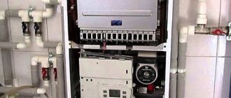
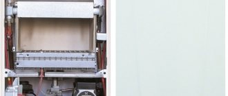
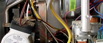
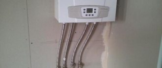
The boiler design consists of the following components:
- Primary and secondary independent heat exchangers.
- Circulation pump with automatic air removal and two-speed operation (Grundfos).
- Burner with stainless steel tips (Polidoro).
- Three-way valve with servo drive.
- Expansion tank 6 l.
- Control board (Honeywell).
The operation of the installation is to heat the coolant by forced passage through the heat exchanger. The hot heating agent in the three-way valve is mixed with the colder return flow in a given proportion and receives the desired temperature, after which it is sent to the heating circuit.
Water enters the boiler and is heated to a set temperature in a secondary heat exchanger. All operations are constantly monitored by a self-diagnosis system, which, if a problem is detected, displays a message in the form of an error code.
Malfunctions and error codes of the Baxi gas boiler
The microprocessor control and monitoring system of a modern gas boiler detects a malfunction and displays an error code indicating a particular malfunction in the operation of the boiler components and assemblies.
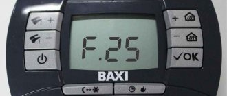
Error code on the display of the BAXI gas boiler. The display backlight flashes synchronously with the displayed fault code.
The boiler control system reacts differently to the occurrence of a malfunction. Depending on the possible consequences of the malfunction:
- The operation of the boiler is immediately blocked in an emergency. The boiler turns off. Error codes: E01, E02, E04, E07, E25, E27, E40, E41, E42, E43, E50, E62, E65. It is necessary to eliminate the malfunction and restart the boiler using the “R” button (keep pressed for at least 2 seconds).
- The boiler operation stops abnormally, but is not blocked. After the problem is resolved, the boiler will automatically continue to operate with the previous user settings.
- There are errors - warnings that do not require immediate intervention, in which the boiler operation does not stop.
How to turn it on
The boiler is connected to the power supply network only after connecting all pipelines supplying water, heating agent and gas.
It is necessary to carefully check the correct connections, paying special attention to the gas pipeline.
Using a soap solution, check for leaks; if any deficiencies are found, immediately correct them yourself or with the involvement of specialists of the appropriate profile. After this, the boiler can be filled with water by opening the feed tap.
The pressure should be between 0.7 and 1 mbar. When the pressure reaches the desired value, the boiler can be started .
Error codes and causes of malfunctions of Baxi wall-mounted gas boilers
Summary list of fault indications for Baxi wall-mounted gas boilers equipped with a liquid crystal (LCD) display, models Eco Compact, Four Tech, Eco Four, Main Four, Main 5.
E01 (01E) - flame control sensor. Boiler blocking after three unsuccessful ignition attempts:
- There is no gas, the gas valve is closed, low pressure in the gas pipe.
- The phase and neutral wires of the electrical network for phase-dependent boiler models are mixed up.
- The ionization flame control electrode is faulty or dirty.
- The ignition unit or electrodes are faulty.
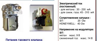
- The gas valve is faulty or incorrectly adjusted.
- Lack of air for gas combustion in the boiler burner
E02 (02E) - heating circuit temperature sensor. Overheating of the coolant in the heating circuit:
- Temperature sensor malfunction.
- Insufficient heat transfer to the sensor - it is recommended to apply thermal paste where the sensor body adheres to the adjacent part of the boiler.
- Insufficient coolant circulation through the heat exchanger due to pump malfunction or air in the system
E03 (03E) - draft sensor (thermostat in boilers with an open or pneumatic relay in boilers with a closed combustion chamber). Insufficient draft in the chimney or flue system:
- Traction sensor malfunction.
- Fan malfunction.
- Reducing the cross-section of a chimney or chimney.
Only for boilers with an open combustion chamber. As a result of the draft failure, the flue gas thermostat overheated and, as a result, an emergency shutdown of the boiler occurred. Check the chimney and whether it has the required draft.
Troubleshooting tips:
Check the chimney for the tightness of the seams and connectors, for compliance with the manufacturer’s recommendations for length and diameter, for the absence of obstacles in the smoke channel (clogging, icing), for blowing and backing of draft by the wind (for the location of the chimney head relative to the roof)
Check the free flow of air into the room where the boiler is installed. There must be an inlet from the street or from an adjacent room with windows.
For a boiler with an open combustion chamber, if the air comes directly from the street, then a supply ventilation opening of 8 cm2 per 1 kW of boiler power is sufficient, but not less than 200 cm2. If the air supply comes from an adjacent room of the building, then the minimum size of the supply ventilation opening should be determined at the rate of 30 cm2 per 1 kW of boiler power. The supply valve in the room with the boiler is installed at a height of no more than 30 cm from the floor. This could be a ventilation grille in the wall or door, or just a gap under the door.
Note: Electric hoods are prohibited in the boiler room.
Check the functionality of the flue gas thermostat.
E04 (04E) - flame control sensor. Frequent, more than six times, loss of flame on the burner:
- The reasons listed in E01 and E42 are
- Exhaust gases entering the boiler supply air duct.
E05 (05E) - heating circuit temperature sensor. No signal from the sensor:
- Malfunction of the heating circuit temperature sensor or open circuit with the electronic board.
E06 (06E) - DHW circuit temperature sensor. No signal from the sensor:
- Malfunction of the DHW circuit temperature sensor or open circuit with the electronic board.
E07 (07E) - NTC flue gas temperature sensor. No signal from the sensor:
- Faulty flue gas temperature sensor or open circuit with the electronic board.
E08 (08E) - electronic board. Error in flame control circuit:
- There is no grounding of the electronic board, there is no contact in the circuit between the board (connector X4) and the power supply box.
- Malfunction of the electronic control board.
E09 (09E) - electronic board. Gas valve safety circuit error:
- Faulty electronic control board.
E10 (10E) - minimum pressure switch for the heating circuit. Insufficient coolant pressure in the heating circuit:
- Check the pressure gauge readings and, if necessary, add water to the heating circuit.
- Minimum pressure switch faulty.
E12 (12E) - differential hydraulic pressure switch. There is no signal from the pressure switch:
- The circulation pump does not work.
- The heating system is contaminated.
- Insufficient coolant circulation (filter clogged, hydraulic resistance of the heating system is high).
- Malfunction of the pressure switch (membrane, microswitch, impulse tube)
E13 (13E) - differential hydraulic pressure switch. False signal from the pressure switch: stuck contacts of the pressure switch microswitch.
E22 (22E) - electronic board. Boiler shutdown due to low voltage in the electrical network, less than 162 V:
- The voltage in the electrical network does not meet the standard.
- The electronic board is faulty.
E25 (25E) - heating circuit temperature sensor. The rate of temperature increase in the heating circuit is more than 1 oC/sec:
- The circulation pump does not work.
- The heating system is contaminated.
- Insufficient coolant circulation (filter clogged, hydraulic resistance of the heating system is high).
- The heating circuit temperature sensor is faulty.
E26 (26E) - heating circuit temperature sensor. Exceeding the coolant temperature by more than 20 °C from the set one:
- The circulation pump does not work.
- The heating system is contaminated.
- Insufficient coolant circulation (filter clogged, hydraulic resistance of the heating system is high).
- The heating circuit temperature sensor is faulty.
E27 (27E) - DHW circuit temperature sensor. Incorrect sensor position:
- The DHW circuit temperature sensor is installed incorrectly.
- The DHW circuit temperature sensor is faulty.
E32 (32E) - temperature sensors for the DHW and heating circuits. Exceeding the heating temperature above 95 ° C twice in a row. Reducing the water temperature in the DHW circuit by 3 °C:
- Presence of scale in the bithermic heat exchanger.
- Malfunction of the NTC temperature sensor of the DHW circuit.
E35 (35E) - flame control sensor. Flame presence signal after the burner is turned off:
- The gas valve is faulty and does not completely shut off the gas supply.
- Moisture on the electronic board of the boiler.
- Interference coming from the electrical network. It is necessary to install a voltage stabilizer with galvanic isolation from the electrical network, and check the proper grounding of the boiler.
E36 (36E) - flue gas temperature sensor. The flue gas NTC sensor is faulty.
E40 (40E) – flue gas temperature sensor. GDC does not pass cyclic flue gas temperature tests:
- The flue gas NTC sensor is faulty.
- Obstruction of the chimney or air supply channel.
E41 (41E) - gas valve. GDC does not pass cyclic tests for ionization current:
- There is no gas, the gas valve is closed.
- The flame control electrode is faulty or dirty.
- Gas valve is faulty.
- Gas valve not calibrated.
E42 (42E) - fan. GDC fails initial tests. Boiler blocking after three unsuccessful attempts:
- The fan is faulty.
- Obstruction of the air supply channel.
E43 (43E) - electronic board. Blockage due to possible blockage of the air supply or too low gas pressure:
- Reasons described in E40 and E41.
- Inconsistency of the quality of supply electricity with the requirements of the standard (low voltage, interference)
E50 (50E) – NTC flue gas temperature sensor. Blockage due to flue gas temperature rising above 180 °C:
- Insufficient coolant circulation.
- The flue gas NTC temperature sensor is faulty.
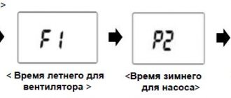
E55 (55E) - gas valve. Gas valve not calibrated. It is necessary to perform calibration (parameters F45 and F48 of the service menu).
E62 (62E) - flame control electrode. Triggering of safety devices in the absence of stabilization of the flame signal or flue gas temperature:
- The flame control electrode is faulty or dirty.
- The NTC flue gas temperature sensor is faulty.
E65 (65E) - electronic board. Triggering of safety devices due to frequent, 10 times within 10 minutes, clogging of the air supply channel: reasons described in E40 and E41.
E96 (96E) - electronic board. Low voltage in the power supply network.
E97 (97E) - electronic board. The voltage frequency in the electrical network differs from 50 Hz.
E98 (98E) - electronic board. Internal error on the electronic board. Incorrect board parameter configuration:
- The parameters have not been configured depending on the boiler type.
- Parameters F03 and F12 of the service menu are set incorrectly.
- Electronic board malfunction.
E99 (99E) - electronic board. An internal error on the electronic board, which accumulates as a result of interference from the power supply network and leads to an independent reboot of the boiler.
The “exclamation mark within a triangle” icon flashes on the display . The boiler is operating at minimum power. The chimney/air duct is clogged or the gas inlet pressure is too low. To reset the fault, temporarily turn off the request for heat production from the heating or DHW system. If the problem persists, contact an authorized service center.
The “radiator” and “faucet” icons flash alternately on the display Scale has formed or the DHW temperature sensor is incorrectly positioned. Attach the clamp of the DHW temperature sensor to the pipe and check the contact with the temperature-sensitive element. Check the DHW temperature sensor (*). Check the primary heat exchanger for scale (when drawing water from the DHW circuit, the temperature of the domestic water leaving the boiler does not increase, while the temperature of the heating water supply to the heating circuit rises rapidly; in addition, the water flow is too low due to partial blockage heat exchanger).
DHW temperature sensor and heating supply temperature sensor: resistance value is about 10 kΩ at 25 °C (resistance decreases with increasing temperature). Flue gas temperature sensor: resistance value is approximately 49 kΩ at 25 °C (resistance decreases with increasing temperature).
More articles on this topic:
⇒ How to reduce the high gas consumption of a boiler for heating a house ⇒ DHW boiler for a double-circuit boiler or water heater ⇒ Setting the pressure in a heating system with a membrane expansion tank
More articles on this topic
- Sound insulation - sound insulation of a house, apartment
- There is formaldehyde in the house, the source is chipboard, OSB, plywood, mineral wool
- House made of large-format porous ceramic blocks
- Warm lightweight masonry mortar for laying block walls
- Norms and rules for planning a private house, cottage
- How to make a shelf with your own hands in a garage, shed or storage room
- Technology for insulating facades and exterior walls of a house with do-it-yourself mineral wool
- Floating floor - soundproofing floors in the house
Pressure setting
To increase the pressure, a make-up valve is used, and to release the pressure, a drain valve is used.
The optimal value is considered to be 0.7-1 mBar. Usually Baxi boilers independently maintain the desired value, but sometimes failures occur. If there is a constant drop that does not disappear after the system is recharged, then there is an OM leak somewhere.
This could mean either leaking pipes or radiators, underfloor heating systems or other external elements.
Often the problem occurs due to a faulty bleed valve. An abnormal increase in pressure may be due to a malfunction or open make-up valve or damage to the expansion tank membrane.
Technology
The connection is made with the boiler and thermostat turned off. According to the instructions for both devices, the corresponding jumper is removed from the control board, and a thermostat is connected to the contacts.
Technologically, this process does not present any difficulty, but for an unprepared person who is afraid to delve into the complex electronics of the equipment, it may seem impossible. In such cases, it is necessary to invite a specialist who can perform qualified installation and connection of the thermostat.
Usually work starts from the boiler:
- With the unit turned off, remove the protective cover to gain access to the control board.
- Remove the jumper on the corresponding contacts according to the instructions.
- Connect the ends of the connecting wire to them.
- The wire is pulled to the location where the thermostat is installed and secured to the wall.
- Connect the device itself, connect it to the power supply.
- Start and configure the operating mode.
Selection of paint and varnish material
Previously, it was easier to choose paint, since the assortment was scarce. There are many paints on store shelves today, but not all of them can be used on concrete. It all depends on the operating conditions. Having considered the features, advantages and disadvantages, you can choose what to paint your concrete floor, ceiling or walls.
Oil-based paints and varnishes
The products are made on an oil base. It has long been used for painting interior and exterior surfaces. However, due to the toxic composition due to solvents, it is better not to use it inside. Has a pungent odor. Advantages:
- Affordable price.
- Withstands the negative impact of the street, is not afraid of moisture and other atmospheric factors.
- A durable and beautiful coating is created.
- Oil-based paint can be susceptible to dust and dirt, but it is easy to clean with gentle products.
- Long service life.
- Good adhesion.
- Large selection of colors.
Flaws:
- Strong smell. Requires waiting for weathering before moving in.
- Toxicity.
- Long drying time, 24 hours or more.
- Has low elasticity, if the concrete cracks, the paint will tear.
- The color is unstable. The drying oil will turn yellow as it is used.
To conclude, oil paint for concrete walls is good if you need to repaint a storage area or other exterior surfaces. After all, it is cheap and practical. But it is better not to use it for work around the house or garage.
Water based paint
Water emulsion and dispersion are an excellent option for interior painting. It is water-based, so it has many advantages. There are no harmful substances in the composition. It can be used to paint concrete walls, ceilings and interior floors. There are façade paints for exterior use. The packaging indicates for what purposes the composition can be used.
Advantages:
- Environmentally friendly.
- Not afraid of moisture.
- Dries quickly.
- Has no smell.
- Easy to use.
- Paints can be sold in white and tinted by hand.
As for the disadvantages, the only thing we can note is the cost. It is low, but oil formulations are cheaper.
Acrylic paint
A universal option, it can be used to paint concrete ceilings, floors, walls inside and outside. It is based on acrylates, which give the composition special properties. The packaging indicates for what purposes it is used: “Ceiling”, “Facade”, “For walls”. Acrylic compositions are also used for artistic painting.
Advantages:
- Environmentally friendly.
- Not afraid of mechanical impact.
- Elastic.
- Vapor permeable, the walls will breathe without condensation.
- Has a stable color throughout its entire service life.
- Possibility of tinting.
- Long service life.
- Not afraid of moisture.
The downside is the cost. It is high. But if you consider the benefits, the price is justified. When choosing what to paint a concrete wall with, you can safely buy alkyd compounds.
Silicate based
It is also called glass paint, as it is based on liquid glass. Thanks to this, a durable film is created on the surface after painting, protecting the structure of the concrete surface. Suitable for indoor and outdoor surfaces.
Advantages of silicate paints:
- Not afraid of chemical exposure.
- Has stable color.
- Strong and durable.
- Protected from fire.
- Not afraid of moisture.
- Resistant to biological factors (development of mold and other microorganisms).
- Very wear-resistant.
Their disadvantages are that they are expensive, and contain toxic substances, so when working with them, it is important to take care of respiratory protection
Impregnations for concrete
Painting walls requires preparation. Before the process, it is better to coat the surface with a special impregnation. This will preserve the surface from dirt, moisture and aggressive environments. The impregnation will penetrate the concrete structure and strengthen it. The compositions are made on an acrylic base, polyurethane or epoxy resins. In addition, preliminary application will reduce paint consumption. After all, concrete has a porous structure and absorbs liquids well.
After applying the impregnation, the wall will dry in a few hours (exact time on the packaging). After this, the wall, floor or ceiling will be ready for painting. The impregnation itself is transparent and may also have additional properties, for example, antiseptic. Having considered the features of paints, you can choose what to paint your concrete floor with.
Temperature adjustment
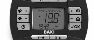
To increase or decrease the heating agent temperature, there are “+” and “-” buttons to the right and left of the display (on older models there is a special regulator; turning clockwise increases the temperature and vice versa).
If a room thermostat is used, adjustments are made from it, and only limit values are set on the boiler.
When setting the temperature, do not change the parameters in large increments. It is necessary to change the mode smoothly, giving some time to overcome the inertia of the system. This will soften the transition to another mode and extend the life of the boiler.
Types of devices
The choice of a remote thermostat for a gas boiler is based on taking into account several characteristics, including the type of connection. Uninterrupted operation is ensured by contact of the remote module with the device that controls the operation of the gas boiler. From a constructive point of view, there are a couple of main options:
- cable models connected to a gas boiler via wires;
- wireless models with remote maintenance.
Mechanical
- durability;
- low cost;
- possibility of repair;
- resistance to voltage surges.
The main disadvantages of mechanics include not very precise adjustment and the likelihood of an error within 2-3 ° C, as well as the need to periodically adjust the indicators manually.
Electronic
In most cases, electronic thermostats for gas boilers are represented by a remote sensor with a display and a special control element responsible for the operation of the boiler. Currently, for this purpose, models with a timer are used that monitor the air temperature and change it according to the desired schedule, as well as electronic analogues. Main advantages of electronic devices:
- remote control;
- the smallest error;
- Possibility of installation in any room;
- adjusting the air temperature according to the schedule;
- the fastest possible response to temperature changes.
Almost instantaneous response to changes in indoor air temperature allows for significant savings in energy resources. The only disadvantages include the fairly high cost of such modern devices.
Programmable
The so-called “smart” equipment has decent functionality, which includes temperature control, hourly adjustment and programming according to the days of the week. Particularly popular are liquid crystal models, which have a very convenient and intuitive interface, as well as built-in Wi-Fi.
Important advantages of programmable models:
- the presence of a “day-night” function;
- significant energy savings;
- programming the mode for a long time;
- possibility of remote control of the entire system.
Gas heating boilers are equipped with devices with built-in SIM cards, which allows you to make adjustments using the most ordinary smartphone. The disadvantages of any programmable models include the rather high cost of these devices.
Wired and wireless
Wired thermostats typically have mechanical or electronic controls. Such devices are fixed only through a wired system designed to connect to gas heating equipment. The range of action, as a rule, does not exceed 45-50 meters. In recent years, programmable models of wired room thermostats have been increasingly installed.
Wireless devices include a working part for installation directly near the heating device, as well as a tracking element with a display. Sensors can be equipped with a touch screen display or push-button control. Operation is provided by a radio channel. The simplest models are capable of turning off or supplying gas. More complex devices also provide a special program for settings in order to make changes to the specified parameters.
