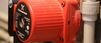
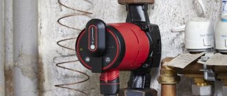
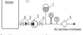
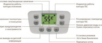
The Danish company's Grundfos UPS pump is widely known for its excellent performance. The Grundfos concern deservedly and rightly occupies first place in the global pumping equipment market. The Danish company has more than 60 years of experience in designing and implementing innovative solutions into production. Designers use a unique program for selecting Grundfos pumps, and confidently push European products to the main positions of the contractor, performing tasks in all areas of water supply and sanitation, including heating aspects.
Since its inception, the company has been offering solutions and equipment that are far superior to its time. The leading place on the pedestal allows us to call the Grundfos company a trendsetter in the design and production of pumping equipment. The main conceptual task at Grundfos is to teach designers, builders, and customers how to select pumping equipment taking into account increasing the energy efficiency of the task at hand.
The main advantage of a wet rotor is absolute silence of operation, despite continuous load. Residents of country houses and the private sector appreciated the innovation of the Danish company; the Grundfos pump brought the capabilities of the heating system to a new qualitative level, increasing its efficiency many times over.
Despite the reduced efficiency indicators compared to the traditional, separate layout of the hydraulic part and the electric motor, the wet rotor of the Grundfos concern occupies a leading position in sales volume. The buyer is ready to pay a high price for the coziness of his home and the comfort of his loved ones.
Grundfos UPS pump. Review
We will begin our journey into the world of Grundfos pumps with an introduction to the household series of circulation pumps. Back in 1959, the company introduced its first circulation pump for heating with the same name Grundfos. All models in the series are successfully used in the forced heating system of private houses. A special place in the series is occupied by time-tested UPS pumps.
Each Grundfos UPS pump is equipped with a three-speed switch, allowing it to be more accurately matched to the hydraulic parameters of the system. The pump is manufactured in two versions with different frequencies: 50 Hz for Russia and 60 Hz for European consumers. The series is used in both open and closed heating systems.
Structurally, UPS pumps are manufactured using “wet-rotor” technology; in a word, the hydraulic part of the pump and the engine form a single whole. In this design, the rotor is completely sealed. This solution eliminates the need for a mechanical seal; instead, only a pair of seals are used. In addition, the pump does not have an impeller for cooling the engine, and the pumped liquid protects it from overheating; it also acts as a lubricating element for the bearings.
The Grundfos UPS pump circulates coolant in heating and air conditioning systems. Special production of pumps made of bronze and even stainless steel solves the problem of using them in hot water supply.
The Grundfos UPS pump currently has 28 products. This diversity is explained by the need for more accurate pump selection in modern heating systems. Despite the abundance of names, all models are easy to remember; you just need to remember the markings.
Grundfos UPS pump marking:
Let's look at the Grundfos UPS 25–40 circulation pump as an example:
- Up – designation of equipment such as a circulation pump;
- S – pump equipment with a speed switch;
- 25 – pipe diameter, mm. (there are pumps of 25, 32, and 40 mm);
- 40 – the highest pressure indicator, dm (40 dm = 4 m) – at the third speed.
Additionally, you can remember that there are pumps with the index “F”, for example the Grundfos UPS 40-100 F pump, this index “F” indicates a flanged connection of the pump to the pipe. In addition, there are pumps with an installation length of 130 mm, then the designation contains the following marking UPS 25-40 130.
Pumps with a length of 130 mm are most often used in confined spaces, for example in wall-mounted boilers.
Equipment with a flange connection, due to the small size of the pump, is used in isolated cases on a 40 mm pipe. In general, standard pumps with an installation length of 180 mm and with connecting nuts for a pipe of 25 mm are used. – one and a half inch nuts G1 1/2″, for a 32 mm pipe. nuts two inches G2″.
It is worth noting that the manufacturer supplies UPS pumps with nuts, which largely frees the buyer from possible misunderstandings, such as purchasing nuts of the wrong size. Recently, additions have been made to the Grundfos pump housing - “noises” have appeared, which are convenient for holding the pump with a wrench.
Grundfos UPS pump with letter “A”
A special model is the Grundfos UPS pump with the letter “A”, which is essentially a hybrid of a circulation pump combined with an air separator. The model allows you to successfully separate the air contained in the water and remove it using an air vent.
The pump is installed in the direction of the water flow from bottom to top. Please note that the air vent itself is not included in the delivery package of the pumps and is sold as an auxiliary accessory. The air vent is installed by screwing in; for this purpose, the housing is equipped with an internal thread Rp 3/8“.
Two main characteristics of a circulation pump
With a long list of technical characteristics of heat pumps, there are two main ones. This is the diameter of the connection pipes and the power of the “accelerator”. These two numbers are considered decisive and are indicated in the name.
Connection pipe diameter
The most important parameter for pump installation, especially with already installed heating systems. This is a numerical value indicated in millimeters and indicating the diameter of the heating pipes that can be connected to the inlet/outlet pipes.
Please note that for connection to the body pipes, taps are made with threaded threads.
Power
Power in heating systems is the ability to raise water to a certain height or pump pressure.
In the marking of Grundfos pumps, the power is indicated in meters multiplied by 10 or atmospheres multiplied by 100. That is, Grundfos with the ability to raise water by 5 meters (pressure 5 meters), the marking will receive the figure 50 or 0.5 atm. (atmospheres).
Example: Circulation pump Wilo Star 30/2, means that the diameter of the connection pipes is 30 mm, the pressure is 2 meters.
In Wilo markings, power is indicated simply in meters.
Example: Grundfos UPS 25 40 (130 mm), means that the diameter of the connection pipes is 25 mm (1/2 inch), the pressure is 4 meters. 130 is the installation length.
Alphanumeric designations of pipelines
GOST 21.205-93 establishes the letter designation of sewer and water pipelines of the following categories:
B – water supply; digital symbols show its purpose, the movement of the working fluid in the system and the quality (source) of water.
K - sewerage pipeline, digital symbols characterize the purpose of the sewerage system and the chemical composition of the discharged wastewater.
T - heat pipes, the numbers show the purpose of the pipeline, the direction of circulation and the type of working fluid.
Rice. 12 Alphanumeric marking of pipelines according to GOST 21.205-93
What is a BP/BP connection?
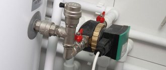
The detachable connection BP/BP of the heating system is a set of adapters that allows you to connect the pipe to the pump body.
- BP/BP means nut/nut;
- BP/HP means nut/thread.
BP/BP adapters are used to connect circulation pumps. Here is an example: Photo of an adapter for connecting a BP/BP pump (1 1/2″ - 1″). This means that the pump nut has a diameter of one and a half inches (32 mm), and the pipe connection nut has an inch (25 mm) diameter.
On the nameplate of the pump and in its description, the diameter G is often indicated; this is the diameter of the union nut for the pump. Pumps are sold complete with connection adapters.
Note: Threaded connection of circulation pumps is typical for low-power household pumps. More powerful pumps are connected via flange connections.
Design and operating principle
The circulation pump, regardless of its type, consists of the following components:
- housing made of corrosion-resistant materials;
- an electric motor consisting of a stator winding and a rotating rotor;
- wheels with blades (impellers) connected to the drive shaft.
When power is applied to the stator winding, the rotor begins to rotate and transmits torque to the impeller. The latter, rotating in the working chamber, creates a vacuum in the heating main, which leads to the suction of water from the pipeline. The coolant that enters inside creates excess pressure and is pushed into the discharge pipe of the heating system. Thanks to the pressure, hot water enters the pipes and radiators and circulates freely through them, overcoming the force of friction.
Grundfos circulation pump markings
Decoding the brand (Type) of the grundfos pump:
- UP – circulation;
- S – there is a power (rotation speed) switching;
- D – twin;
- 30 – diameter (mm dn) of the suction pipe and pressure pipe;
- 60 – max. pressure (meters×10);
- F – connection of pipes through a flange (the letter is missing when threaded);
- N – body material (cast iron body – no letter, letter N – stainless steel body);
- B – bronze body;
- A – the housing has an air outlet;
- K – housing for working with antifreeze (special version).
Letter
We have already told you how to decipher the markings of wires and cables. Single-line electrical circuits also have their own letters, which make it clear what is included in the network. So, according to GOST 7624-55, the letter designation of elements on electrical circuits is as follows:
- Relays for current, voltage, power, resistance, time, intermediate, indicating, gas and time-delayed, respectively - RT, RN, RM, RS, RV, RP, RU, RG, RTV.
- KU – control button.
- KV – limit switch.
- CC – command controller.
- PV – travel switch.
- DG is the main engine.
- DO – cooling pump motor.
- DBH is a high-speed engine.
- DP – feed motor.
- DS – spindle motor.
In addition, in the domestic marking of elements of radio engineering and electrical circuits, the following letter designations are distinguished:
This completes a brief overview of symbols in electrical circuits. We hope that now you know how sockets, switches, lamps and other circuit elements are indicated on drawings and plans of residential premises.
Also read:
Standards
- RF: GOST 26349-84, GOST 356-80, GOST R 54432-2011
- EU: DIN EN 1092-1-2008
- USA: ANSI/ASME B16.5-2009, ANSI/ASME B16.47-2006
©Obotoplenii.ru
Articles on the topic
- Repair and replacement of heating in a new building
- Methods of heating a private house: choosing how to heat the house
- Heating system with single-circuit gas boiler and heated floor, installation diagrams
- Hydraulic separator: description, purpose
- Air heating of country houses
Tips for choosing a device for a heated floor system in your home
How to choose a pump for underfloor heating? Today, the market mainly offers CO pumps with a standard flow rate of about 40 l/min (about 2.5 cubic meters/hour) and a pressure of up to six meters. The flow rate is directly proportional to the pressure value.
When purchasing, you should understand that the flow rate of 40 l/min indicated on the pump will not always correspond to the actual flow rate. Because the latter depends on what the throughput of the floor assembly or the system itself is. A large number of long circuits reduces consumption.
It’s easy to understand this using two graphs: theoretical (for all similar pumps) - No. 1, and real for the 2.5 cubic meter pump considered in the example. with a pressure of six meters - No. 2.
The higher the throughput capabilities of your system, the weaker the pressure on all connected circuits. Those. The more circuits are closed to one mixing unit, the greater the flow rate.
Advantages of devices
Thanks to the special properties of the Wilo pump, the efficiency of the heating system increases significantly. In this case, thin pipes can be used, which, in turn, helps reduce material and fuel costs. Also, when using a pump, the volume of carbon dioxide that is released into the atmosphere is reduced, and the daily consumption of electrical energy is no more than 250 W.
Of course, such a device is not cheap. You will have to pay a large amount for its purchase, but the cost will certainly pay off later when used due to energy savings and durability. The device will not require repair for a long time.
Vilo pumps have many positive properties.
The most important of them are the following:
- After water evaporates, there is no heat loss.
- The operation of the system can be controlled automatically. The device has a liquid crystal screen, a built-in thermostat and other elements that allow control. You can also manually switch the speed of rotation of the working shaft.
- Compared to many circulation pumps from other brands, Wilo devices are quite compact and therefore do not take up much space.
- The motor and rotor have a multi-stage protection system that helps prevent failure due to sudden surges in voltage in the electrical network.
- The motor operates silently, making it possible to install the device in residential buildings.
Wilo pumps are used in small rooms of several hundred square meters. The selection is carried out according to such parameters as power, volume of circulated water, room area and pressure height. The last parameter is the most important.
You can see how to distinguish an original pump from a fake in the following video:
—
CONDITION 1
RESULTS ¾Ð»ÑÑинÑÑве ÑÑÑеÑÑвÑÑÑÐ¸Ñ Ñимволик окÑÑжноÑÑи. RESULTS, RESULTS RESULTS ° RESULTS. RESULTS ÑÑ Ð¾ÑÑием жиÑной ÑÑÑелки, помеÑенной внÑÑ Ñи конÑÑÑа Ñимвола, а ÑегÑлиÑÑемоÑÑÑ Ð¿Ð¾Ð´Ð°Ñи — дР»Ð¸Ð½Ð½Ð¾Ð¹ Ñонкой ÑÑÑелкой, пеÑеÑекаÑÑей ÑÑÐ¾Ñ Ð ºÐ¾Ð½ÑÑS под ÑгÐ" ом. â
RESULTS 1) 3000 rs / 3000 rs. â
ROOM 1/2 У - опÑÑкаеÑÑÑ. â
бознаÑение наÑоÑа вклÑÑÐ°ÐµÑ ÑÑи бÑквÑ: Ц — ÑеР½ÑÑобежнÑй, Ð — наÑоÑ, С — ÑекÑионнÑй и двР° ÑиÑла, пеÑвое из коÑоÑÑÑ — подаÑа наÑоÑа Q, м3 / Ñ, вÑоÑое - Ð½Ð°Ð¿Ð¾Ñ Ð, м ÑÑ. жидкоÑÑи. â
RESULTS дÑÑÑим обÑазом: а) ЦР— ÑенÑÑобежнÑй, геÑмеÑиÑнÑй; б) дÑобÑ: ÑиÑлиÑелÑно-миналÑÐ½Ð°Ñ Ð¿Ð¾Ð´Ð°Ñа в м3 / Ñ, знаменаÑÐµÐ»С — номиналÑнÑй Ð½Ð°Ð¿Ð¾Ñ Ð² м ÑÑ. жидкоÑÑи; 1) SYSTEM; - ¾ÑÑÑ ÑлекÑÑодвигаÑелÑ, кÐÑ; д) поÑледнÑÑÑиÑÑа - обознаÑение конÑÑÑÑкÑиР› влениÑ. â
RESULTS дÑÑÑим обÑазом: а) ЦР— ÑенÑÑобежнÑй, геÑмеÑиÑнÑй; б) дÑобÑ: ÑиÑлиÑелÑно-миналÑÐ½Ð°Ñ Ð¿Ð¾Ð´Ð°Ñа в м3 / Ñ, знаменаÑÐµÐ»С — номиналÑнÑй Ð½Ð°Ð¿Ð¾Ñ Ð² м ÑÑ. жидкоÑÑи; 1) SYSTEM; - ¾ÑÑÑ ÑлекÑÑодвигаÑелÑ, кÐÑ; д) поÑледнÑÑÑиÑÑа - обознаÑение конÑÑÑÑкÑиР› влениÑ. â
ROOM RESEARCH - ( Ð), Ð¥Ð. â
| конÑолÑнÑй наÑÐ¾Ñ 4Ð - 8. â |
registry That's it. RESULTS ½Ð¾Ð³Ð¾ паÑÑÑбка в мм, ÑменÑÑеннÑй в 25 Ѱз, а ÑиÑÑÑ Ð¿Ð¾Ñле бÑкв — коÑÑÑиÑÐ¸ÐµÐ½Ñ Ð±ÑÑÑÑоÑодноÑÑ 10 points ROOM . â
| бÑий вид. â |
registry I'm sorry. RESULTS 15150 - 69) ¸Ðµ ÐÐСТа. ÐÑабÐ". 2.2 RESULTS оÑов Ñипа Ð. â
| RESULTS а ÑекÑионного Ñипа.| OPTIONAL RESEARCH RESULTS. â |
RESULTS . â
RESULTS . â
ROOM 25 Ñаз; бÑква - Ñип наÑоÑа; коÑÑиÑÐ¸ÐµÐ½Ñ Ð±ÑÑÑÑоÑодноÑÑÐ ¸ наÑоÑа, ÑменÑÑеннÑй в 10 Ñаз и окÑÑгленнÑй. â
Types of schemes
A diagram in design documentation is a document that graphically shows the symbols of the main elements of communications or parts of products, equipment, as well as the connection (connection) between them. Their distinctive feature in comparison with drawings is the lack of image scale and correspondence to the real spatial arrangement of elements.
The types and types of schemes are regulated by GOST 2.701-84, the most famous of them, usually used in individual housing construction:
- Electrical.
- Hydraulic.
- Energy.
- Gas.
- Combined.
According to their purpose, schemes are divided into the following categories:
Structural. A structural or block diagram shows the main components of the product, their purpose and mutual connections, and reveals the functioning algorithm. Parts of a system or device are depicted inscribed in rectangles, diamonds or other shapes, connected by indicating relationships with lines with arrows.
Developed at the initial stage of designing a product or system, they are useful for studying its operating principle.
Functional. They reveal the processes occurring in the system, a specific product or its individual components. Necessary for determining the principle of operation, technical parameters of products, used in adjustment, adjustment, repair, monitoring of the physical parameters of the working environment and equipment.
Rice. 4 Sewerage diagrams in drawings according to GOST 21.601-79 - examples
Fundamental
Connections. Wiring diagrams show connections between individual units or parts of systems, simple products, and complex technical equipment. Laying methods and methods of connecting system elements, connection points are established, indicating the input and output points of the joined fragments.
Connections. The diagrams show the connection of external communications, products, and equipment to system devices. The type of connections is disclosed, indicating their technical characteristics.
Are common. They show the main system components and connections between them in relation to specific installation conditions and are linked to equipped objects of various types.
Locations. They specifically show the placement of various communication nodes and equipment relative to objects and each other, indicating distances in length units.
Each diagram in the drawing corresponds to its own alphabetic and digital markings, regulated by GOST 2.701-84.
From the above list, the most complex and detailed are the schematic diagrams, which are most often used in the design of various systems and equipment.
Rice. 5 Designation of filter and elements for general use according to GOST 21.205-93
Areas of application
The Wilo brand produces pumps designed for different purposes and therefore having different characteristics.
With the help of such a pump, you can water the beds directly from a well, borehole or the nearest body of water.
The scope of their application is wide and varied:
- Wilo devices are used in heating systems in closed circuits.
- They are used in the water supply of private houses and in wells for water extraction.
- Such pumps are also suitable for pumping out groundwater when creating basements and cellars.
- They are also used on construction sites when working with contaminated water.
- Owners of private suburban areas have found good use for them, in particular those who grow plants on their plots.
The Vilo pump can operate in the most difficult conditions, and it does not matter what the temperature of the water circulated through the pipes will be or what the pressure will be.
You can connect the device yourself without any problems. For this purpose, it is equipped with special spring terminals. It does not have a fan, so there is virtually no noise during operation.
