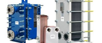
Design and principle of operation
The design of a gasketed plate heat exchanger includes:
- a stationary front plate on which the inlet and outlet pipes are mounted;
- fixed pressure plate;
- movable pressure plate;
- package of heat exchange plates;
- seals made of material that is heat-resistant and resistant to aggressive environments;
- upper supporting base;
- lower guide base;
- bed;
- set of coupling bolts;
- Set of support feet.
This arrangement of the unit ensures maximum intensity of heat exchange between working media and compact dimensions of the device.
Design of a gasketed plate heat exchanger
Most often, heat exchange plates are made by cold stamping from stainless steel with a thickness of 0.5 to 1 mm, however, when using chemically active compounds as a working medium, titanium or nickel plates can be used.
All plates included in the working kit have the same shape and are installed sequentially, in a mirror image. This method of installing heat exchange plates ensures not only the formation of slot channels, but also the alternation of primary and secondary circuits.
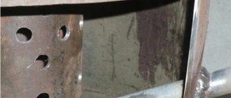
Each plate has 4 holes, two of which provide circulation of the primary working fluid, and the other two are isolated by additional contour gaskets, eliminating the possibility of mixing working fluids. The tightness of the connection between the plates is ensured by special contour sealing gaskets made from a material that is heat-resistant and resistant to active chemical compounds. The gaskets are installed in the profile grooves and secured using a clip lock.
Operating principle of plate heat exchanger
The effectiveness of any plate maintenance is assessed according to the following criteria:
- power;
- maximum temperature of the working environment;
- bandwidth;
- hydraulic resistance.
Based on these parameters, the required heat exchanger model is selected. In collapsible plate heat exchangers, the throughput and hydraulic resistance can be adjusted by changing the number and type of plate elements.
The intensity of heat transfer is determined by the flow regime of the working medium:
- with laminar flow of the coolant, the intensity of heat transfer is minimal;
- the transition regime is characterized by an increase in the intensity of heat transfer due to the appearance of turbulence in the working environment;
- The maximum intensity of heat exchange is achieved with turbulent movement of the coolant.
The performance characteristics of the plate heat exchanger are calculated for a turbulent flow of the working medium.
Depending on the location of the grooves, there are three types of heat exchange plates:
- with “soft”
channels (grooves are located at an angle of 600). Such plates are characterized by slight turbulence and low heat transfer intensity, however, “soft” plates have minimal hydraulic resistance; - with “medium”
channels (corrugation angle from 60 to 300). The plates are a transitional option and are distinguished by average turbulence and heat transfer rates; - with “hard”
channels (corrugation angle 300). Such plates are characterized by maximum turbulence, intense heat transfer and a significant increase in hydraulic resistance.
To increase the efficiency of heat exchange, the movement of the primary and secondary working fluid is carried out in the opposite direction. The heat exchange process between the primary and secondary working fluids occurs as follows:
- The coolant is supplied to the inlet pipes of the heat exchanger;
- When moving the working media along the corresponding circuits formed from heat-exchange plate elements, intense heat transfer occurs from the heated medium to the heated one;
- Through the outlet pipes of the heat exchanger, the heated coolant is directed to its destination (heating, ventilation, water supply systems), and the cooled coolant again enters the working area of the heat generator.
Operating principle of a plate heat exchanger
To ensure efficient operation of the system, complete tightness of the heat exchange channels is required, which is ensured by sealing gaskets.
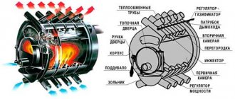
Principle of operation
The basis of the collapsible type design are plates made by cold stamping from thin-walled sheet metal - most often aluminum alloy, sometimes steel, etc. The plates are rotated 180 degrees and distributed “right” - “left”.
At the end of the assembly of the structure and sealing with special gaskets, the profiles themselves turn into a whole network of convenient passage channels, creating separate circuits within which coolants circulate: two elements - heating-cooling, the second, on the contrary, heating-cooling. They move in countercurrent, increasing the temperature pressure. Other elements of the mechanism:
- a fixed plate equipped with inlet and outlet pipes (supporting “skeleton” where a set of plates is located);
- console guides, where the plates themselves + sealing gaskets are strung;
- movable plate;
- threaded rods;
- special plates that change the direction of flow.
Here you can see the diagram as a whole.
Requirements for gaskets
To ensure complete tightness of the profile channels and prevent leakage of working media, sealing gaskets must have the necessary heat resistance and sufficient resistance to the effects of an aggressive working environment.
The following types of gaskets are used in modern plate heat exchangers:
- ethylene propylene (EPDM). Used when working with hot water and steam in the temperature range from -35 to +1600C, unsuitable for fatty and oily environments;
- NITRIL gaskets (NBR) are used for working with oily working media, the temperature of which does not exceed 1350C;
- VITOR gaskets are designed to work with aggressive working environments at temperatures not exceeding 1800C.
The graphs show the dependence of the service life of seals on operating conditions:
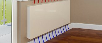
We recommend: Convector heater for home and garden: pros and cons
As for attaching the sealing gaskets, there are two ways:
- on glue;
- using a clip.
The first method is rarely used due to the complexity and duration of installation; in addition, when using glue, maintenance of the unit and replacement of seals is significantly more complicated.
The clip lock ensures quick installation of plates and ease of replacement of failed seals.
Kinds
Collapsible
The most popular option, suitable for working with coolants of different bases (in liquid, vapor or gaseous state, with different environments, pressure and temperature).
They are collapsible plate heat exchangers that are extremely flexible in design settings. To increase or decrease the area of the heat exchange process, new plates are installed or old ones are removed. It is easy to dismantle and disassemble for cleaning or repair work. Users do not need to contact third parties (service), which allows them to significantly save money.
A type of collapsible heat exchanger is semi-welded. One part of it is welded, the second is dismountable. In practice, it is used infrequently; greater preference is always given to the collapsible version, it is more convenient.
Soldered
The advantage of a soldered heat exchanger: increased pressure and temperature resistance. Disadvantage: if there are changes in the operating mode and changes in thermal power indicators, you will have to completely replace the device; it does not have flexible settings.
Repairing breakdowns is also quite difficult: the structure must be completely removed and taken to a service center, since attempting to carry out repairs yourself is unlikely to be successful. The absence of a heat exchanger during the repair period will lead to prolonged downtime in production and financial costs for the organization.
Design of heat exchange equipment
Corrugated plates are made of stainless steel (most often acid-resistant) and are connected to each other using sealing gaskets. This structure is then attached to the frame (size depends on the equipment model). In this case, the plates can be removed or added at any time (both before installation and during operation), which allows you to achieve the most effective heat transfer coefficient.
Technical parameters of models
When studying the assortment, rely on the following technical characteristics:
- the material from which the panels are made - these can be refractory compounds, thin sheet steel, pure titanium;
- the maximum permissible medium pressure in the unit usually does not exceed 25 kgf/cm²;
- in each node the number of plates used starts from 7-10, their number is determined by the future area of application;
- devices can withstand coolant temperatures of no higher than 180°C.
One working unit is capable of providing a heat exchange area in the range of 0.1-2100 square meters. m.
Advantages of plate heat exchangers
The main purpose of such devices is the transfer of heat between coolants that are separated from each other (mixing of working media is excluded).
Due to their design features, plate heat exchangers have a number of significantly different technical parameters:
- compactness (the heat exchanger is selected according to the required heat transfer rates; the smaller the differences, the fewer plates are used);
- versatility (can be used in heating points at various facilities and used depending on the required power);
- cost-effectiveness (the cost depends on the number of plates, there is a choice, repairs cost by replacing a worn (damaged) package of plates, and not the entire system);
- temperature range is from -50 to +200 ˚С;
- ease of maintenance (cleaning is carried out by unscrewing the bolts of the pressure plate, then the plates with sealing gaskets are removed and washed).
Heat exchanger piping
As a rule, the installation of such thermal power equipment is provided for in individual boiler houses of multi-apartment residential buildings or industrial enterprises, as well as in heating points of centralized heat supply systems. The goal is to obtain water for domestic hot water needs at a temperature of up to 70 ºС or a coolant up to 95 ºС when using steam and high-temperature hot water boilers.
Due to its small dimensions and weight, installation of the heat exchanger is quite simple, although powerful units require a foundation. In any case, the foundation bolts are poured, with the help of which the device is securely fixed in its place. The coolant is always supplied to the upper branch pipe, and the return pipeline is connected to the fitting located below it. The heated water supply is connected, on the contrary, to the lower pipe, and its outlet to the upper one. The simplest wiring diagram for a plate heat exchanger is shown below:
The coolant supply circuit must have its own circulation pump installed on the supply pipeline. In accordance with the rules, in addition to the working pump, a reserve pump of the same power is installed in parallel. If the DHW system has a return circulation line, then the connection diagram takes the following form:
Here, the heat of water flowing through a closed DHW circuit is used, cold water from the water supply is mixed with it, and only then the mixture enters the heat exchanger. The outlet temperature is controlled by an electronic unit that controls the valve on the coolant supply line. Well, the last scheme is a two-stage one, which allows you to use the thermal energy of the return line of the heating system:
The scheme allows you to save significantly by removing excess load from boilers and using the available heat to the maximum. It should be noted that in all schemes filters are installed at the entrance to the high-speed heat exchanger. The reliable and durable operation of the unit depends on this.
Characteristics and calculation
Plates and seals as the main parts of heat exchange devices are made from materials that differ in their performance and characteristics. When choosing a particular product, the main role is played by its purpose and scope of application.
If we consider heating systems and hot water supply, then in this area, plates that are made of stainless steel and plastic seals made of special rubber NBR or EPDM are most often used. The presence of stainless steel plates makes it possible to work with a coolant heated to 120 degrees; in another case, the heat exchanger can heat the liquid up to 180°C.
Gaskets are located between the plates for sealing
When using heat exchangers in the industrial sector and connecting them to technological processes exposed to oils, acids, fats, alkalis and other aggressive media, plates made of titanium, bronze and other metals are used. In these cases, the installation of asbestos or fluorine rubber gaskets is required.
The choice of heat exchanger is carried out taking into account calculations that are made using special software.
During calculations it is necessary to take into account:
- consumption of heated liquid;
- initial temperature of the coolant;
- heating fluid costs;
- required heating temperature.
The heating medium that flows through the heat exchanger can be heated water to a temperature of 90-120°C or steam with a temperature of up to 170°C. The type of coolant is selected taking into account the type of boiler equipment used. The dimensions and number of plates are selected so as to produce a coolant with a temperature that complies with current standards - no higher than 65°C.
The heat exchanger can be made of different types of metal
It must be said that the main technical characteristics, which are also considered the main advantages, are the compact dimensions of the equipment and the ability to provide a fairly significant flow rate.
The range of exchange areas and probable costs for the devices is quite high. The smallest of them, for example, from Alfa Laval, have a surface size of up to 1 m² and at the same time provide the passage of a coolant amount of up to 0.3 m³/hour. The largest devices have a size of about 2500 m² and a flow rate that exceeds 4000 m³/hour.
Advantages and Limitations
If we compare plate structures with shell-and-tube structures, the former have a higher heat transfer coefficient with an identical area. Capable of transmitting more power while maintaining original size and weight.
Other advantages of the device:
- extensive modernization opportunities to increase heat transfer rates;
- accessibility and easy maintenance - cleaning by disassembly.
Restrictions apply to:
- temperature used - maximum 180 degrees;
- operating pressure – maximum 2.5 MPa (25 bar).
The efficiency of plate heat exchangers is considered the highest among similar designs.
Types of plate heat exchangers
Plate heat exchangers are divided according to the degree of accessibility of the heat exchange surface for mechanical cleaning and inspection:
- collapsible
- semi-collapsible (semi-welded)
- non-separable (soldered and welded)
The most widely used are plate heat exchangers , in which the plates are separated from one another by rubber seals. Installation and dismantling of these devices is carried out quite quickly, cleaning the heat exchange surfaces requires little labor.
Operating principle and unit diagram
The design, calculation and flushing of plate heat exchangers for heating are based on the fact that the unit functions due to the presence of 4 holes:
- 2 openings for inflow and outlet of hot working fluid;
- 2 holes to ensure hermetically sealed joining of the plates and prevent mixing of coolants - this task is performed by seals.
The movement of liquid in the unit is carried out according to the principle of flow vortex. As a result, due to the relatively low resistance to the movement of the working medium, the intensity of thermal energy transfer increases. Also, due to the low resistance during the passage of liquid, the amount of scale in the internal cavities is reduced.
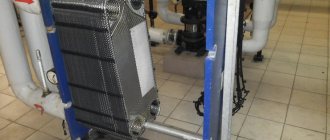
What does a plate heat exchanger look like?
The operating principle of a plate heat exchanger, based on loops and vortices, promotes multiple energy exchanges. As a result, the maximum efficiency of the unit is achieved, which is positively influenced by the outlet of the pipes into both types of panels - clamping and fixed.
The heat exchanger design is ideally suited to the operating conditions: the number of plates increases in proportion to the potential power requirements of the system. The number of operating elements has a direct impact on the efficiency and performance of heating or cooling equipment.
Connecting plate heat exchangers
The classic connection diagram for plate heat exchangers has coolant inlet and outlet pipes on the front plate. In most cases, the inlets and outlets are located in such a way as to ensure a counterflow of heat exchange media. The operation of a plate heat exchanger with a counterflow of working media is shown in the video:
There are designs of plate heat exchangers in which the coolant inlet and outlet pipes are located both on the front and rear plates:
Connection to the inputs and outputs of working media is carried out using flanged connections, welded connections (steel pipe) or threaded connections. It is also possible that there is no pipe at the inlet or outlet of the coolant. In this case, holes with internal threads for studs are made around the hole on the plate, with the help of which you can connect a pipeline with coolant using a heat-resistant rubber or rubber seal.
Story
Plate heat exchangers were first introduced in 1923 for the pasteurization of milk, but are now used in many applications in the chemical, petroleum, climate control, refrigeration, dairy, pharmaceutical, food and medical industries. This is due to their unique advantages such as flexible thermal design (plates can simply be added or removed to meet different thermal or processing requirements), ease of cleaning to maintain strict hygienic conditions, good temperature control (necessary in cryogenic processes) and better heat transfer characteristics.
Plates for plate heat exchangers
Serially produced plate heat exchangers are equipped with plates stamped from sheet metal up to 1 mm thick. The materials used are corrosion-resistant steel, titanium, and special alloys. The plates of a plate heat exchanger have a corrugated surface to turbulize flows in the channels, which increases heat transfer efficiency and prevents the deposition of contaminants. The corrugations of the plates usually have the cross-section of an equilateral triangle. The steeper the angle at which the plate corrugations are located, the greater the resistance created in the channels; the sharper the angle, the lower the resistance and the higher the flow speed.
Plates for gasketed plate heat exchangers
Structural characteristics of the heat exchanger and plates
When calculating a plate heat exchanger, it is necessary to take into account that the basis of the device is laid on:
- fixed and pressure plates;
- pipes (inlet and outlet) with various connections;
- mounting stand;
- guides;
- threaded hardware.
Energy is transferred between coolants through plates made of rust-resistant inert materials. The latter are processed by stamping, their thickness varies between 0.4-1 mm. When assembled, the unit consists of tightly fitting thin panels with slotted channels. All elements have a contour recess on the front side into which a rubber seal is placed (this ensures a tight fit of the elements).
The plates are uniform in shape and material; they can be made of stainless steel, titanium, refractory alloys (selected depending on the application). For the production of seals, complex polymers based on synthetic rubber are used; they can be used with glycol and non-aggressive media, steam and high-temperature liquids, oil-containing and oil-based coolants.
Plate heat exchanger piping diagrams
There are several ways to connect a PHE to a heating system. The simplest is considered to be parallel connection with a control valve, the circuit diagram of which is shown below:
PHE parallel connection diagram
The disadvantages of such a connection include increased load on the heating circuit and low efficiency of water heating at a significant temperature difference.
Parallel connection of two heat exchangers in a two-stage scheme will ensure more productive and reliable operation of the system:
Two-stage parallel connection diagram
1 – plate heat exchanger; 2 – temperature regulator; 2.1 – valve; 2.2 – thermostat; 3 – circulation pump; 4 – hot water flow meter; 5 – pressure gauge.
The heating medium for the first stage is the return circuit of the heating system, and the heated medium is cold water. In the second circuit, the heating medium is the coolant from the direct line of the heating system, and the heated medium is the preheated coolant from the first stage.
We recommend: Chimney damper: definition, types, pros and cons, installation methods
Types of heat exchangers for domestic hot water systems
Among the many types of different heat exchangers, only two are used in domestic conditions - plate and shell-and-tube. The latter have practically disappeared from the market due to their large dimensions and low efficiency.
Plate heat exchanger DHW
is a series of corrugated plates on a rigid frame. All plates are identical in size and design, but follow each other in a mirror image and are separated by special gaskets - rubber and steel. As a result of strict alternation between paired plates, cavities are formed, which are filled with coolant or heated liquid - mixing of media is completely excluded. Through the guide channels, two liquids move towards each other, filling every second cavity, and also, along the guides, exit the heat exchanger giving/receiving thermal energy.
The higher the number or size of plates in the heat exchanger, the larger the useful heat exchange area and the higher the performance of the heat exchanger. Many models have enough space on the guide beam between the frame and the locking (outer) plate to install several plates of the same size. In this case, additional plates are always installed in pairs, otherwise it will be necessary to change the inlet-outlet direction on the locking plate.
Scheme and principle of operation of a hot water supply plate heat exchanger
All plate heat exchangers can be divided into:
- Collapsible (consist of separate plates)
- Soldered (sealed housing, not dismountable)
The advantage of collapsible heat exchangers is the possibility of modifying them (adding or removing plates) - this function is not provided in brazed models. In regions with low quality tap water, such heat exchangers can be disassembled and cleaned of debris and deposits manually.
Brazed plate heat exchangers are more popular - due to the lack of a clamping structure, they have more compact dimensions than a collapsible model of similar performance. selects and sells brazed plate heat exchangers from the world's leading brands - Alfa Laval, SWEP, Danfoss, ONDA, KAORI, GEA, WTT, Kelvion (Kelvion Mashimpex), Ridan. From us you can buy a DHW heat exchanger of any capacity for a private house or apartment.
The advantage of soldered heat exchangers compared to collapsible ones
- Small dimensions and weight
- More stringent quality control
- Long service life
- Resistance to high pressures and temperatures
Cleaning of soldered heat exchangers is carried out using the in-place method. If, after a certain period of operation, the thermal characteristics begin to decrease, then a reagent solution is poured into the device for several hours to remove all deposits. The break in equipment operation will be no more than 2-3 hours.
Flushing the plate heat exchanger
The functionality and performance of the unit largely depends on high-quality and timely washing. The frequency of washing is determined by the intensity of work and the characteristics of technological processes.
Methodology for cleaning work
Scale formation in heat exchange channels is the most common type of PHE contamination, leading to a decrease in heat exchange intensity and a decrease in the overall efficiency of the installation. Descaling is carried out using chemical washing. If, in addition to scale, other types of contamination are present, it is necessary to mechanically clean the heat exchanger plates.
Chemical washing
The method is used for cleaning all types of PHE, and is effective with minor contamination of the working area of the heat exchanger. To carry out chemical cleaning, disassembling the unit is not required, which can significantly reduce the work time. In addition, no other methods are used for cleaning brazed and welded heat exchangers.
Chemical washing of heat exchange equipment is carried out in the following sequence:
- a special cleaning solution is introduced into the working area of the heat exchanger, where scale and other deposits are intensively destroyed under the influence of chemically active reagents;
- ensuring circulation of detergent through the primary and secondary maintenance circuits;
- flushing heat exchange channels with water;
- draining cleaning agents from the heat exchanger.
During the chemical cleaning process, special attention should be paid to the final rinsing of the unit, since chemically active components of detergents can destroy seals.
The most common types of contamination and cleaning methods
Depending on the working media used, temperature conditions and pressure in the system, the nature of the contaminants can be different, so for effective cleaning it is necessary to choose the right detergent:
- cleaning from scale and metal deposits uses solutions of phosphoric, nitric or citric acid;
- inhibited mineral acid is suitable for removing iron oxide;
- organic deposits are intensively destroyed by sodium hydroxide, and mineral deposits by nitric acid;
- fatty stains are removed using special organic solvents.
Since the thickness of the heat exchange plates is only 0.4 - 1 mm, special attention should be paid to the concentration of active elements in the detergent composition. Exceeding the permissible concentration of aggressive components can lead to destruction of plates and sealing gaskets.
The widespread use of plate heat exchangers in various sectors of modern industry and public utilities is due to their high performance, compact overall dimensions, ease of installation and maintenance. Another advantage of VET is the optimal price/quality ratio.
Where is it used?
The use of plate heat exchangers is almost universal. They can be used in a wide variety of applications, depending on the materials and design of the equipment. There are different models, differing in design and different subtleties of operation, but in total there are four main types:
- collapsible;
- semi-welded;
- welded;
- soldered.
Collapsible ones are installed in heating networks that equip residential buildings and other facilities. They are also found in swimming pools, hot water supply circuits, heating units and refrigerators. Brazed heat exchangers are designed for installation in freezing or ventilation systems, as well as air conditioners, compressors, and other industrial installations.
Welded and semi-welded heat exchangers are widespread and are found in:
- Food Industry;
- pharmaceuticals;
- climatic and ventilation units;
- recovery systems;
- hot water supply, heating;
- cooling units.
Of all the units presented above, collapsible and soldered structures are most often used, because their use is relevant in various fields, regardless of whether a decrease or increase in coolant temperature is required. You may also be interested in flushing accessories.
Collapsible plate types
Advantages
- minimum production costs
- minimum installation cost
- performance is adjustable
- ease of operation and repair
- low operating costs
- downtime is minimal
- low energy consumption
Application
- heating systems
- residential buildings and premises
- swimming pools
- refrigeration and climate control units
- hot water supply systems
- heating points
Criterias of choice
When determining the optimal model of the device, you should rely on the technical characteristics of the product:
- DHW connection diagram;
- level of thermal load;
- parameters of the heating and heated medium.
The last point takes into account information such as inlet and outlet temperatures in winter and summer, potential fluid flow and permissible pressure losses, and the percentage of power reserve. This information is used as a basis when calculating the performance of a plate heat exchanger.
Comparison of plate heat exchangers with shell-and-tube analogues
| Characteristic | Shell and tube heat exchangers | Gasketed plate heat exchangers |
| Heat transfer coefficient (conditionally) | 1 | 3 — 5 |
| The difference (possible) between the temperatures of the coolant and the heated medium at the outlet | Not less than 5-10 °C | 1 - 2 °C |
| Change in heat exchange surface area | Impossible | Acceptable within a wide range, a multiple of the number of plates |
| Internal volume (conditionally) | 100 | 1 |
| Assembly connection | Welding, rolling | Detachable |
| Accessibility for internal inspection and cleaning | Non-separable, difficult to access, simple replacement of parts is impossible; only flushing possible | Collapsible. Easily accessible inspection, maintenance and replacement of any part, as well as mechanical washing of the plates. |
| Disassembly time | 90 - 120 min. | 15 minutes. |
| Tube (plate) material | Brass or copper | Stainless steel |
| Seals | Non-separable. Simple replacement is not possible | Glueless seals are easily replaced with new ones. The plates are rigidly fixed in the channels. No leaks after mechanical cleaning and assembly |
| Leak detection | Cannot be detected without disassembly | Immediately after occurrence, without disassembly |
| Susceptibility to corrosion at temperatures above 60 °C | Yes | No |
| Sensitivity to vibration | Sensitive | Insensitive |
| Assembled weight (conditionally) | 10 — 15 | 1 |
| Thermal insulation | Required | Not required |
| Operating life up to cap. repairs | 5 – 10 years | 15 – 20 years |
| Dimensions (conditionally) | 5-6 | 1 |
| Special foundation | Required | Not required |
| Cost (conditionally) | depending on the purpose and connection diagram 0.75 – 1.0 | 1,0 |
Sources
- https://masterok-remonta.ru/otoplenie-i-ventilyatsiya/plastinchatyy-teploobmennik.html
- https://www.teploprofi.com/teploobmennik-razborniy/
- https://sn22.ru/catalog/plastinchatie-teploobmenniki/
- https://sn22.ru/articles/printsip-raboty-teploobmennikov/
- https://kaminguru.com/sistema-otoplenija/shema-plastinchatogo-teploobmennika.html
- https://www.teploobmenka.ru/oborud/art-phe/
- https://teploobmennic.ru/blog/sovety-pokupatelyam/plastinchatyy-teploobmennik/
- https://www.teploprofi.com/plastinchatiy-teploobmennik/
How do you like the article?
Sergey Vladimirovich
Ask a Question
Heat transfer systems and features: the task of the heat exchanger
Plate heat exchangers can be used in various systems in industrial facilities and residential buildings.
In multi-storey buildings, preference is given to collapsible devices
In an apartment building
A standard dismountable device is often involved in connecting heating and hot water supply systems. There are several reasons for its installation in an apartment building:
- service life - from 25 years, but seals must be changed every 5-10 years;
- the device is easy to disassemble and can be repaired;
- the power can be adjusted independently by changing the number of plates.
This type of heat exchanger for heating is also suitable for industrial areas.
Self-repair of heating equipment is unacceptable
In a private house
In a private home, it is recommended to use a soldered heat exchanger for several reasons:
- suitable for aggressive environments;
- The service life of the device is 15 years;
- guarantees high efficiency due to minimal loss of thermal energy and high level of heat transfer;
- Since there are no seals in the design, leaks are impossible.
Assembling the device is quite simple and does not take much time.
The equipment requires regular checking of seals and descaling
Nuances of installation and connection
The heat exchanger is used only in conjunction and does not imply independent use. During installation, the unit is surrounded by auxiliary equipment, such as check valves, control and measuring devices in the form of thermometers and pressure gauges, shut-off valves (manual valves and gate valves), and circulation pumps.
The connection is made according to one of the following schemes:
- single-stage parallel (independent) method;
- two-stage mixed;
- two-stage sequential.
Installation of a plate heat exchanger
In the first case, there is a significant saving of usable space in the installation area. The key advantage of this method is its ease of execution (which is important in conditions of repair, maintenance, or replacement of a unit). The disadvantage of the technique is the inability to heat a cold working environment.
With a two-stage mixed method, the temperature of the incoming coolant increases due to the reverse flow, as a result, the efficiency of the bundle increases by 35-40%. But in this case, to ensure hot water supply, it will be necessary to provide two heat exchangers in the system, which increases the cost of purchasing and installing equipment.
The sequential two-stage method allows you to increase the efficiency of using the working environment and stabilize the load on the network. Compared to the parallel circuit, the coolant costs are reduced by 50%, and compared to the mixed method - by 25%. The only drawback of the solution is the impossibility of fully automating the heating unit.