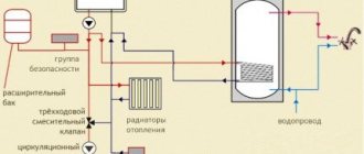
Heating: Artificial heating of the room during the cold season to compensate for heat losses and maintain normal temperature with an average lack of supply of 50 hours/year. The internal heat supply systems of a building should be understood as heat supply systems for heating, water heaters, hot water supply systems, air heaters for air handling units, air conditioners, air heating units, air heat curtains, etc. (SP 60.13330.2012).
The main task of the heating system is to create comfortable conditions for visitors to the building. The goals of automation of heating systems are:
- Efficient and economical use of heat sources;
- Facilitating system management for the building maintenance service or the owner of a private home;
- Forecasting equipment maintenance;
- Load distribution and balancing on the building’s heating network;
- Preventing equipment failure;
- Reducing the influence of the “human factor”;
- Reduced utility costs.
A combination of automation systems for heating, ventilation and air conditioning systems form an automatic microclimate control system in a building.
Types of heating systems
Heating systems are classified according to the following criteria.
According to the type of heat exchange between the heater and the environment:
Convective heating . In this case, the transfer of thermal energy occurs along with the movement of volumes of hot and cold air: the warm air flow rushes upward, the cold air flows down. Due to the heat transfer mechanism, convective heating is impossible through any impenetrable barriers, incl. transparent.
Radiant heating . This is a type of heating in which heat is transferred by radiation. From the Sun to the Earth or from the heated surface to the observer.
Convective-radiant heating . Mixed mechanism. Most heating devices (radiators, convectors, heated floors and walls) transfer heat in this particular way; the optimal option is when there is an approximately equal (50/50) ratio of convective and radiant heat.
By type of coolant:
Water heating . Today the most common type of heating, which comes in the following types:
- Radiator heating, in which the following types of radiators can be used: cast iron, steel, aluminum, bimetallic, stone, ceramic, as well as convectors.
- Warm water floor. In this case, heating communications are laid under the floor covering.
- Baseboard heating. In this case, each section of the warm baseboard is a small convector with a casing, and installation is carried out like installing a regular radiator.
- Water infrared heating (“warm ceiling”). When installing such a system, a large infrared panel is attached to the ceiling, which is a heat source.
- Combined systems: include elements of the above heating systems.
Air heating . Air systems include systems in which the coolant is heated air. In supply ventilation, such systems can be local or distributed.
In local systems, heating and air supply are carried out directly in the heated room using heating and heating and ventilation devices.
In distributed systems, air is heated in an air heating unit and supplied to rooms through ducts.
In addition, there is fire-air heating, in which heat comes from stoves and fireplaces. With this type of heating, the coolant is either practically absent, or it is hot flue gases.
Heating systems without coolant.
- Electric heating systems. In such systems, electrical energy, converted into heat, heats the room rather than the coolant, for example, electric fireplaces, infrared electric panels, electric radiators or floors.
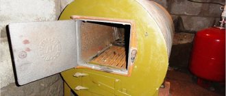
- Gas systems. In such systems, heat is generated by the combustion of a gas-air mixture. An example is gas fireplaces. picture of galley heating
The concept of balancing
For a heating system to operate as efficiently as possible, it is important that it releases heat in such a way that it warms all rooms evenly. This will not only provide warmth and comfort in the house, but will also help reduce heating costs.
Heating systems can be divided into two types:
- Single-pipe or double-pipe. In them, the heated coolant moves through pipes from the heating boiler, giving off some of the heat to each radiator. Then the liquid that has lost heat enters the boiler again. After this, the cycle described here is repeated again.
- System with manifold connection. It has a distribution device, from which pipes go separately to each radiator. The adjustment occurs for each of them independently.
The last category includes heating systems that use not only radiators, but also heated floors.
The general principle of balancing is similar in different cases. Each radiator has an inlet valve. If they are all fully deployed, then the greatest heat loss in the first category of systems will occur in the first device. Further, increasingly cooled water will flow. To prevent this from happening, a valve is tightened in the initial batteries. Thus, the heat consumption will decrease and it will be enough for other heating devices.
This procedure must be done in several steps to achieve the desired result. Between attempts, the batteries are given time to warm up properly.
For heating systems, regulation occurs by regulating the volume of incoming heated liquid. There should be so much of it that it is enough to heat each room.
The floors are adjusted in the same way, increasing or decreasing the heat supply. If the floors use heating based on the use of electrical energy, adjustment is made according to different rules, simply changing the settings.
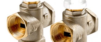
Flow regulators, bypass valves, control valves, and pressure regulators are used to carry out adjustments. The layout of their installation depends on the specific type of heating system.
Thermostats occupy a special place. They have the most complete functionality. The device contains an electronic temperature sensor. The work takes place under the control of an electronic circuit. There is a simple and intuitive control panel.
The use of such electronic devices allows adjustments to be made at minimal cost. If necessary, it is possible to program the heating operation. For example, it is possible to reduce the heating temperature if the family is absent from the house for several days.
Heating system elements
Which elements can be used (and automated).
Boilers . The main element of any system, since this is where the process of fuel combustion occurs, after which the heat released during this process is transferred to the coolant (water or antifreeze).
According to the type of energy carrier, boilers are:
- gas;
- electrical;
- liquid fuel;
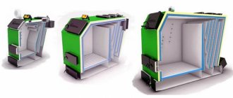
- solid fuel;
- combined;
- alternative, for example, solar collectors.
Depending on the number of coolant circulation circuits, boilers are:
- Single-circuit – intended for heating only;
- Multi-circuit – also used to heat water or turn on a heated floor system.
Burners . They are installed on gas boilers and can be fan-powered (with a supercharger) or atmospheric. Fan burners are noisier, but can operate at any incoming gas pressure.
Heating temperature chart . In apartment buildings, public and industrial buildings, boilers and burners are replaced by thermal power plants or thermal power plants. From the station, through the heating main systems, the heated steam enters the district heating district, and from it, in turn, to the building’s heating and heating system. From the heated coolant, in accordance with the temperature schedule, heat is transferred through ITP heat exchangers to the heating, ventilation and hot water circuits. At the outlet of their heat exchangers, the temperature of the coolant returning to the network must correspond to the temperature schedule.
Example of a temperature graph. Click to expand
| Outdoor air temperature Тнв, оС | Temperature of network water in the supply pipeline Т1,оС | Water temperature in the supply pipeline of the heating system Т3, оС | Water temperature after heating system T2, оС | |||
| 150 | 130 | 115 | 105 | 95 | ||
| 8 | 53,2 | 50,2 | 46,4 | 43,4 | 41,2 | 35,8 |
| 7 | 55,7 | 52,3 | 48,2 | 45,0 | 42,7 | 36,8 |
| 6 | 58,1 | 54,4 | 50,0 | 46,6 | 44,1 | 37,7 |
| 5 | 60,5 | 56,5 | 51,8 | 48,2 | 45,5 | 38,7 |
| 4 | 62,9 | 58,5 | 53,5 | 49,8 | 46,9 | 39,6 |
| 3 | 65,3 | 60,5 | 55,3 | 51,4 | 48,3 | 40,6 |
| 2 | 67,7 | 62,6 | 57,0 | 52,9 | 49,7 | 41,5 |
| 1 | 70,0 | 64,5 | 58,8 | 54,5 | 51,0 | 42,4 |
| 0 | 72,4 | 66,5 | 60,5 | 56,0 | 52,4 | 43,3 |
| -1 | 74,7 | 68,5 | 62,2 | 57,5 | 53,7 | 44,2 |
| -2 | 77,0 | 70,4 | 63,8 | 59,0 | 55,0 | 45,0 |
| -3 | 79,3 | 72,4 | 65,5 | 60,5 | 56,3 | 45,9 |
| -4 | 81,6 | 74,3 | 67,2 | 62,0 | 57,6 | 46,7 |
| -5 | 83,9 | 76,2 | 68,8 | 63,5 | 58,9 | 47,6 |
| -6 | 86,2 | 78,1 | 70,4 | 65,0 | 60,2 | 48,4 |
| -7 | 88,5 | 80,0 | 72,1 | 66,4 | 61,5 | 49,2 |
| -8 | 90,8 | 81,9 | 73,7 | 67,9 | 62,8 | 50,1 |
| -9 | 93,0 | 83,8 | 75,3 | 69,3 | 64,0 | 50,9 |
| -10 | 95,3 | 85,6 | 76,9 | 70,8 | 65,3 | 51,7 |
| -11 | 97,6 | 87,5 | 78,5 | 72,2 | 66,6 | 52,5 |
| -12 | 99,8 | 89,3 | 80,1 | 73,6 | 67,8 | 53,3 |
| -13 | 102,0 | 91,2 | 81,7 | 75,0 | 69,0 | 54,0 |
| -14 | 104,3 | 93,0 | 83,3 | 76,4 | 70,3 | 54,8 |
| -15 | 106,5 | 94,8 | 84,8 | 77,9 | 71,5 | 55,6 |
| -16 | 108,7 | 96,6 | 86,4 | 79,3 | 72,7 | 56,3 |
| -17 | 110,9 | 98,4 | 87,9 | 80,7 | 73,9 | 57,1 |
| -18 | 113,1 | 100,2 | 89,5 | 82,0 | 75,1 | 57,9 |
| -19 | 115,3 | 102,0 | 91,0 | 83,4 | 76,3 | 58,6 |
| -20 | 117,5 | 103,8 | 92,6 | 84,8 | 77,5 | 59,4 |
| -21 | 119,7 | 105,6 | 94,1 | 86,2 | 78,7 | 60,1 |
| -22 | 121,9 | 107,4 | 95,6 | 87,6 | 79,9 | 60,8 |
| -23 | 124,1 | 109,2 | 97,1 | 88,9 | 81,1 | 61,6 |
| -24 | 126,3 | 110,9 | 98,6 | 90,3 | 82,3 | 62,3 |
| -25 | 128,5 | 112,7 | 100,2 | 91,6 | 83,5 | 63,0 |
| -26 | 130,6 | 114,4 | 101,7 | 93,0 | 84,6 | 63,7 |
| -27 | 132,8 | 116,2 | 103,2 | 94,3 | 85,8 | 64,4 |
| -28 | 135,0 | 117,9 | 104,7 | 95,7 | 87,0 | 65,1 |
| -29 | 137,1 | 119,7 | 106,1 | 97,0 | 88,1 | 65,8 |
| -30 | 139,3 | 121,4 | 107,6 | 98,4 | 89,3 | 66,5 |
| -31 | 141,4 | 123,1 | 109,1 | 99,7 | 90,4 | 67,2 |
| -32 | 143,6 | 124,9 | 110,6 | 101,0 | 94,6 | 67,9 |
| -33 | 145,7 | 126,6 | 112,1 | 102,4 | 92,7 | 68,6 |
| -34 | 147,9 | 128,3 | 113,5 | 103,7 | 93,9 | 69,3 |
| -35 | 150,0 | 130,0 | 115,0 | 105,0 | 95,0 | 70,0 |
Read more about ITP automation.
Air valves . Serve to remove air from the system. Such valves are found in heating radiators and risers. Many are familiar with the Mayevsky manual valve.
Expansion tanks . As the temperature rises, the internal hydraulic pressure in a closed system filled with water increases, and to prevent an accident, excess water enters the expansion tank. If the system does not have a boiler, then an expansion tank is not required.
Circulation pumps . They are used for the movement of coolant in a system with forced circulation.
Pipeline system . They are used to move coolant through them; they are made of steel, copper and polymer.
Radiators, heated floors . Final heating devices. They are used for heating the room; they are made of steel, cast iron, aluminum and bimetallic.
sensors , flow meters, speed controllers and thermostats. All these tools are used to monitor system parameters, eliminate accidents, and control the system, manually or automatically.
Automatic temperature control of diesel water and oil
5.2 Automatic control of diesel water and oil temperature
When fuel burns in diesel cylinders, a large amount of heat is released, which heats the cylinder walls, pistons, covers, exhaust manifolds, etc. If heat were not removed from these parts, then the operation of the diesel engine would be impossible - the high temperature would not allow the supply of oil to the rubbing parts of the cylinder-piston group, would cause warping of parts, the appearance of cracks, etc. To remove heat from a diesel engine, water and oil are used as coolants. Water cools the diesel cylinders, cylinder covers and the rest of the exhaust tract. The oil cools the pistons and other rubbing parts. In modern diesel engines, in addition, it is necessary to cool the charge air, and in the hydraulic drive - its oil. By forcing water and oil to circulate between the heated parts of the diesel engine and cooling devices in a closed circuit, the required portion of the heat from the heated parts is removed by coolants and dissipated into the surrounding air. Experience shows that on modern diesel locomotives approximately 8...12% of the heat generated in the diesel cylinders is removed with cooling water, 6...10% with oil, and 4...6% with water cooling the charge air.
The process of heat dissipation into the environment is quite complex. This is due to the variable operating mode of the diesel engine, in which the amount of heat generated in the cylinders depends on the position of the controller and the load, as well as variable outside air temperatures, which can range from -50 °C to +40 °C. At the same time, to ensure the reliability and efficiency of diesel operation, the coolant temperature should not fluctuate within wide limits, but should be maintained at a certain level. In this regard, cooling devices must be able to regulate coolant temperatures.
The coolant is supplied to the tubular sections of the radiators of the cooling system, located at the front on the sides of the body in a special closed shaft. The coolant flows through a variety of externally finned sections of tubes from one collector to another. In this case, air supplied by the fan passes between the tubes of the sections along the entire front of their location. The air, passing between the tubes and their fins, picks up heat from the coolant and, heated, is thrown out of the shaft to the outside.
The shaft has louvers on top and sides that can be opened and closed using an electro-pneumatic drive or manually. The blinds protect the sections from mechanical damage, and opening and closing them allows you to change the flow of air supplied to the sections. When the fan is on and the blinds are open, air is drawn in from the atmosphere through the side blinds and pushed out through the top blinds.
Most series of diesel locomotives are equipped with automatic control of the opening and closing of the shutters to protect the radiator sections from hypothermia. The operating principle of an automatic device for protecting a diesel engine from hypothermia based on water temperature and oil temperature is the same.
Air is supplied to the cylinders 11, 7 of the side 12 and top 5 shutters from the air line of the locomotive through an electro-pneumatic valve 9, which turns on the thermal relay 8 depending on the temperature of the water (for the first circulation circuit) or oil (for the second circuit) at the outlet of the diesel engine.
The opening and closing of the blinds on modern diesel locomotives, as well as the turning on of the fan, are carried out automatically using eight single-limit sensors - temperature relays (thermal relays) of the RDK or KRD type, installed on the pipelines that drain water and oil from the diesel engine, and on the pipeline that supplies water to the air cooler. The thermal relays are adjusted to the following response limits: for water cooling the diesel engine: 76 °C - opening of the blinds; 84 °C - fan on; 96 °C - load dump; for diesel oil: 67 °C - opening of the blinds; 76 °C - fan on; 80°C - light alarm; for water cooling the charge air: 25 °C - opening of the blinds; 55 °C - turn on the fan.
Fan drives are divided into: mechanical from a diesel engine using cardan shafts, an angular gearbox and a friction clutch; hydromechanical from a diesel engine with the inclusion of a variable-fill hydrodynamic coupling in the mechanical system; hydrostatic without a mechanical connection between the fan shaft and the diesel shaft and electric with an individual AC motor for each fan. Diesel power consumption for fan drives accounts for a significant share - 5 ... 6%.
On the 2TE10V diesel locomotive, when the thermal relay is activated, the electrical signal is sent to the corresponding electro-pneumatic valve, which opens the access of compressed air to the corresponding pneumatic cylinder of the blind drive or the cooling device fan clutch.
The cooling device fan is driven from the rear distribution gearbox through cardan shafts, fan fluid couplings with an angular gearbox and a vertical cardan shaft. The fluid coupling is filled with oil through a fitting from the diesel system. When the fluid coupling is filled with oil, rotation from the drive shaft to the driven horizontal shaft is transmitted due to the pressure of the oil flow thrown from the blades of the rotating pump wheel onto the blades of the turbine wheel. When the bell cavity is completely filled with oil, the turbine wheel has a maximum rotation speed (2 ... 3 °/o less than the pump wheel rotation speed due to “sliding”). When the bell is partially filled with oil, the rotation speed of the turbine wheel will decrease depending on the degree of filling of the bell. By adjusting the degree of filling of the bell with oil, you can adjust the rotation speed of the fan, to which rotation is transmitted from a horizontal shaft through a bevel gearbox and a vertical cardan shaft.
The automatic water and oil temperature control system includes water and oil thermostats, a hydraulic piston drive of the variable-fill hydraulic coupling rack, microswitches, electro-pneumatic valves with pneumatic cylinders for driving the blinds. Temperature regulators for water (TRV) and oil (TRM) are located on both sides of the hydraulic piston drive (servomotor) of the fluid coupling filling rack. The thermostat rods, with the heads of the adjusting bolts screwed into the rods, rest against the horizontal pin connecting the cheeks of the lever 6 of the rigid feedback of the servomotor. When the temperature of the coolant (water or oil) rises above normal, the solid filler ceresin, located in the coil of the thermal cylinder 13 and washed by the coolant, expands and acts on the rubber plug 14 with the rod 15. The rod 15, moving in the sleeve 17, moves the lever along the slot of the sleeve 16, screwed into the rod, thereby releases lever 18, which, under the influence of a spring, closes the contacts of the microswitches of the water cooling circuit or the oil cooling circuit. Microswitches activate electro-pneumatic valves that control the opening of the side and top blinds. Each thermostat operates on the blinds of its own cooling system only. The upper blinds open when any microswitch is turned on, and close only when both microswitches are turned off.
Under certain conditions, opening the shutters may be sufficient to cool the water in the radiator sections. If the temperature of the controlled liquid begins to decrease, the volume of the solid filler of the thermal cylinders decreases and the rubber plug 14 is moved by the rod 15 under the action of the spring to its original position. The rod, with the lever 16 screwed into it, retracts the lever 18 and opens the contacts of the microswitch, thereby closing the blinds.
If opening the blinds fails to maintain the temperature at the required level and it continues to rise, the fan turns on and further temperature regulation is ensured by changing its rotation speed using a variable-fill fluid coupling. The hydraulic coupling operating mode is controlled as follows. Ceresin, heated in a thermal cylinder washed by liquid, moves rod 15 through plug 14, which, after being turned on by means of lever 18 of the blinds, moving further, rests the adjusting bolt against the pin of feedback lever 6, turning the lever clockwise. Together with lever 6, the spool rod 7 moves and moves the piston 10 to the right. Following the piston 10, the rack of the adjusting device moves, which meshes with the gear of the drive sleeve 21. The teeth cut at the second end of the sleeve 21 are meshed with the teeth of the gears 20. In this case, the fan rotation frequency increases. The process of increasing the fan frequency will continue until the temperature of the coolant stops increasing. In this case, the increase in the volume of ceresin stops and the thermostat rod 15 stops. Piston 10, moving to the right in the process of regulating the temperature of the liquid, moves spool 7 with lever 6. Thus, thanks to lever 6, the power piston always moves the spool towards the end of its movement, i.e. to the neutral position. Therefore, lever 6 is called a feedback lever.
When the temperature drops, the movement of the mechanism parts occurs in the opposite direction. The spool 7, under the action of the spring, moves to the right and the piston 10 moves to the left until the feedback lever 6 sets the spool to the overlap position. Therefore, the operation of the feedback lever 6 can be imagined as swinging relative to a fixed point, therefore, the stroke of the power piston will be proportional to the stroke of the thermostat rod.
For the entire range of adjustable rotation speed of the fluid coupling shaft (rack stroke 42 mm), approximately 5 mm of thermostat rod stroke is required, which is 5 °C temperature change (heating by 1 °C causes about 1 mm of thermostat rod stroke). From the above it is clear that when the operating mode of the cooling device changes, the temperature of the liquid will also change within 5 °C.
When switching to manual control, the temperature of the water and oil is regulated by turning the side and top blinds, as well as the fan, on and off. When you turn on the fan toggle switch on the control panel, compressed air is supplied to the pneumatic cylinder, which moves the piston to the left, compressing the spring, and through the pusher sets the spool to the extreme left position. This sets the maximum fan wheel speed for each driver controller position.
The hydrostatic drive of the fans of the cooling device of the TEP70 diesel locomotive consists of four hydraulic machines of the MH250/100 type, two of which operate in the hydraulic displacement pump mode and two in the engine mode. Unlike a hydrodynamic drive, which uses the kinetic energy of a fluid, a hydrostatic drive is based on the use of energy from the static pressure of a fluid. From the diesel shaft through a step-up gearbox (multiplier) 1, two hydraulic pumps 2, 3 are driven, pumping oil from the filter tank 10 and supplying it to hydraulic motors 7, where the energy of oil pressure is converted into mechanical energy of rotation of fans 8. In the nominal operating mode of the diesel engine, the hydraulic pumps provide maximum oil supply, forcing the hydraulic motors to rotate the fans at a maximum frequency of 1330 rpm. Changing the fan speed is achieved by bypassing the oil after the hydraulic pumps past the hydraulic motors. Changing the bypass is performed by thermostats 5, 6, which have temperature sensors washed with water or diesel oil. Under the influence of the ambient temperature, the volume of the sensor filler changes, causing the thermostat spool to move, which reduces or increases the oil bypass from the hydraulic pumps, bypassing the hydraulic motors.
To maintain normal operating oil temperature in the hydraulic drive system (60 ... 70 °C), oil cooling is provided in one oil-air section 9, installed in the cooling device shaft. Regulation of the rotation speed of the fan wheels of the cooling device is achieved by changing the oil pressure supplied to the hydraulic motors. The process of regulating the fan rotation speed is controlled by thermostats installed in the water and oil pipelines at the diesel outlet.
The command element of the thermostat is a thermal balloon (thermal sensor) 8 filled with ceresin, a crystalline substance with a high coefficient of volumetric expansion. The temperature sensor is covered on top with a rubber diaphragm 7. To enhance thermal conductivity, the temperature sensors are filled not with pure ceresin, but mixed with PACK aluminum powder in a weight ratio of 30% aluminum powder and 70% ceresin.
The temperature sensor works as follows. When the filler passes into the liquid phase, the central thickened part of the rubber diaphragm 7 moves upward, pushing out the rubber plug 6 along the channel of the sensor body. To increase the linear movement of the pusher of the working body associated with it) relative to the linear movement of the diaphragm that perceives the pressure of the filler, the plug is made with an area ratio lower and upper parts 1:6. Thus, the volumetric expansion of the filler in a thermal cylinder placed in the coolant in the design of the thermostat is converted into linear movement of the pusher 5, which in turn moves the spool 3, which controls the supply of fluid to the hydraulic motor. For temperature sensor 8, the pusher stroke is 6.6 mm at a water temperature of 69±2 °C and 10.5 mm at a water temperature of 80±2 °C and no more than 12 mm at a water temperature of 90±2 °C. Relatively small linear movements of the diaphragm and plug help reduce their wear.
Static unevenness of temperature control is allowed up to 12 °C and can be reduced by increasing the sensor gain. The magnitude of static temperature unevenness is also affected by the location of the temperature sensor. Therefore, they should be installed only in a “hot” coolant, i.e., the flow of water or oil at the outlet of the diesel engine.
Temperature regulators of the TEP70 diesel locomotive are installed on the water (one) and oil (two in series) pipelines at the diesel engine outlet. At a liquid temperature of 69±2 °C, washing the temperature sensor, the volume of the filler, having passed from the solid phase to the liquid, will begin to expand and through the diaphragm 7, plug 6 and pusher 5 will move the spool 3 upward. In this case, the working edge of the spool will gradually begin to overlap the annular slot. The oil will begin to flow to the hydraulic motor, which will rotate the fan wheel. As the size of the gap decreases, the amount of oil supplied to the hydraulic motor will increase, and its rotation speed will increase. The amount of oil in the drain will decrease. When the spool completely closes the gap, all the oil flow from the pump will flow to the hydraulic motor, the output shaft of which with the fan wheel will rotate at the maximum (design) speed. In this case, the temperature of the liquid (water or oil) washing the temperature sensor must be above 80±2 °C. As the temperature of the liquid decreases, the filler contracts, the gap will increase and some of the oil will begin to flow to the drain.
At temperatures below 69±1 °C, spring 2 returns the spool to the lower position, all the oil goes to drain without going to the hydraulic motors. The fans stop rotating and further cooling of the water and diesel oil stops. Thus, within the selected control interval, the thermostat smoothly changes the rotation speed of the hydraulic motor (fan).
At intermediate coolant temperatures, the drain gap is partially closed, and the fan wheel will operate at a frequency proportional to the amount of oil supplied to the hydraulic motor. Thus, stepless control of the hydraulic motor rotation speed is established using a thermostat.
The temperature of diesel water and oil is regulated not only by changing the fan speed, but also by opening or closing the shutters of the cooling devices, depending on the temperature of the water and oil.
The cooling device of the 2TE116 diesel locomotive is controlled both by an automatic system for regulating the temperature of water and diesel oil, and manually from the driver’s console.
Asynchronous electric motors of rectifier unit fans MV7, traction motors MV5 and MV6, as well as refrigerator fans MV1 ... MV4 receive power directly from terminals 1C1 ... 1C3 and 2C1 ... 2C3 of the stator windings of the traction generator through the contacts of three-pole circuit breakers AB7, AB5, AB6, AB1 ... AB4 and contactors K1 ... K4, respectively, both in diesel idle mode and in traction mode.
Automatic control of the refrigerator is activated by moving the toggle switch TX “Refrigerator Control” to the “Automatic” position when the automatic switch A6 “Refrigerator Control” is turned on and the contacts of the reversing mechanism of the controller B or H are closed. In this case, voltage is supplied to the contacts of the microswitches of temperature sensors-relays 0V, 1V, 2B, 0M, 1M, 2M automatic temperature control systems.
Sensor-relay 0M, when the oil temperature reaches 62 °C, supplies power from the TX toggle switch to the coil of the electro-pneumatic valve VP6 “Opening the left side blinds”. At a water temperature of 75 °C, the contacts of the 0V sensor-relay close, supplying power to the coil of the electro-pneumatic valve VP5 “Opening the right side blinds”.
When the oil temperature reaches 67 °C, temperature sensor-relay 1M supplies power to the contactor coil K4. Contactor K4 turns on the 4MV refrigeration chamber fan motor. At the same time, power is supplied to: - the coil of valve VP4 “Upper left blinds”; — to the valve coil VP6 “Opening the left side blinds.”
When the oil temperature reaches 72 °C, temperature sensor-relay 2M closes the circuit of the contactor coil K3 with its contact. At the same time, the coil of the electro-pneumatic valve VP3 “Upper right blinds” receives power. Contactor K3 with its main contacts turns on the motor-fan of the 3MV refrigerator shaft, and the VP3 valve opens its upper shutters.
In the same way, motor fans 1MV, 2MV of the refrigerating chamber are turned on and their upper blinds are opened; they are controlled by diesel water temperature sensors-relays 1B (operation temperature 79 °C), 2B (operation temperature 83 °C).
The TX “Refrigerator Control” toggle switch is moved to the “Manual” position when switching to manual control of the refrigerator. The temperature of water and diesel oil is regulated by turning on the corresponding toggle switches T1, T2 (for water) and T3, T4 (for oil) on the control panel.
Get text
What and how to automate? Basic principles
Depending on the type of coolant heating system, the control and parameters controlled by the automation system will differ.
In general, the operator sets the desired temperature in the room, via the control panel or via a PC, via a remote control in a separate room, etc.
The heating automation system, based on data on the air temperature in the building, the outside air temperature, the time of day, and the presence of people in the room, selects an operating mode and transmits control signals to actuators, which may differ:
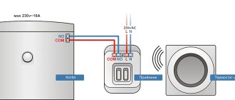
A) To control the electric heating system, devices are used that control the power of the electric current: bimetallic thermostats operating on the “on/off” principle, or thyristor voltage regulators, with the help of which, when the voltage decreases, the power consumption of the device is also reduced. As an example, we can recall an electric convector, the user sets the required temperature, and the thermostat maintains the temperature by turning on and off the power supply to the device.
B) To control a heating system with a coolant circuit, devices are used that regulate the temperature and flow of the coolant. At the same time, adjusting the temperature of the coolant is possible only in autonomous systems with boilers and heaters, for example, in private houses; for centralized heating systems, the temperature of the incoming and outgoing coolant flows is given by the graphs:
- from large thermal power plants: 150/70°C, 130/70°C or 105/70°C;
- from boiler houses and small thermal power plants: 105/70°C or 95/70°C.
Thus, at large facilities, room temperature control can only be carried out using devices that change the coolant flow in the heating network and maintain it at a given level, so as not to go beyond the temperature schedule.
Tools and devices for balancing
To independently adjust the heating radiators and heated floors of a private house, you will need a minimum of equipment:
- electronic contact thermometer;
- screwdriver;
- a thumb or wrench for rotating the balancing valve stem (a hexagon is usually used);
- sheet of paper, pencil.
Reference. Professional plumbers often use a thermal imager, which gives a clear picture of the heating of all heating devices. The device is expensive, so we’ll make do with simpler means.
To measure temperature, it is better to use an electronic contact-type device.
Instead of the specified thermometer, it is allowed to use a remote (non-contact) pyrometer. Please note: the device measures the temperature of shiny surfaces with a small error. This note applies to radiators with new paintwork.
If you do not have a wiring diagram for a residential building, you should sketch it on paper before starting work. The sketch will help you understand the order in which the batteries are connected to the mains and the distance from the furnace room. Also, flush the mud trap at the entrance to the boiler and heat the system to a temperature of 70-80 ° C, regardless of the street weather.
A great help in setting up is the modern Grundfos Alpha 3 circulation pump, which accurately shows the depth of adjustment via a mobile application. The downside is the decent price of the unit (starts at 240 USD).
Main components of the heating automation system
- temperature (indoor, outdoor, coolant) and pressure sensors, which provide a constant supply of information about the state of the heating system;
- thermostats (setters, thermostats) that regulate the coolant supply;
- drives and actuators (valves, circulation and make-up pumps, frequency regulators) perform the function of regulatory and safety mechanisms that ensure reliable and trouble-free operation of the system.
- automation panels (controllers, expansion modules) that control the heating system
Regulation of heat supply in an apartment building
The most common way to provide thermal energy to apartment buildings is central heating. The coolant is supplied through heating mains from central boiler houses or thermal power plants. The heated liquid is received by the heating point.
It performs primary heat metering, ensures supply regulation, and distributes it to consumers. There are other options for heating apartments.
Among the most common: individual heating of an apartment building, heating of a separate apartment.
Each scheme has advantages and disadvantages; the choice of the most convenient one depends on a number of factors: the proximity of highways, their condition, the feasibility of using energy from remote boiler houses. In any case, the design of new communications and the reconstruction of old networks should include the development of mechanisms for regulating the supply of heat to apartment buildings. This is not so much a question of comfort as of saving energy resources.
Automation of the heat supply control process
The existing system of transportation and distribution of thermal energy is far from ideal. Its imperfection is especially acute during the off-season. It often happens that the weather outside is consistently warm, and the radiators stubbornly heat the already warm rooms.
This situation is due to the fact that the only link in the chain of enterprises, communications and coolant supply devices that has the ability to influence the heat supply process is the boiler house or thermal power plant.
But even they do not have the possibility of flexible regulation; they do not have mechanisms that allow them to instantly respond to weather changes.
The ideal option for regulating the heat supply in an apartment building would be a project in which, when implemented, it becomes possible to regulate the temperature of each room separately. This solution allows for individual metering of heat supply, which in turn allows residents not to pay for heat that simply escapes through open vents.
Individual metering of heat supply allows the consumer to independently regulate the amount of thermal energy consumed. This can be achieved by setting the temperature of rooms that are not in use lower, raising it as needed.
Heat supply can be regulated by turning off the taps on the radiators. In addition, you can entrust the regulation process to automation. Modern industry offers various devices that allow you to regulate the room temperature.
Sensors
The sensors are designed to monitor pressure and temperature indoors, outdoors and coolant in the pipelines of the heating system.
Temperature sensors are:
Submersible . Designed to take readings about water heating in pipes. Their installation is carried out in certain areas of the system. These sensors are bimetallic and alcohol
Remote . This type of sensor is installed outside the heating system. Recently, wireless models have become popular, which transmit information using auxiliary electronics, which makes it possible to install them almost anywhere - in a separate room or outdoors.
Pressure sensors can be mechanical - pressure switches (mechanical measurement of pressure difference and electrical conversion) and analog pressure sensors (conversion of pressure directly into an electrical signal, for example, using piezo elements).
Heat supply of a multi-storey building
Heating distribution unit for an apartment building
Heating distribution in a multi-storey building is important for the operational parameters of the system. However, in addition to this, the characteristics of the heat supply should be taken into account
An important one is the method of supplying hot water - centralized or autonomous.
In most cases, a connection is made to the central heating system. This allows you to reduce the current costs in the estimate for heating a multi-storey building. But in practice the level of quality of such services remains extremely low. Therefore, if there is a choice, preference is given to autonomous heating of a multi-storey building.
Autonomous heating of a multi-storey building
autonomous heating of a multi-storey building
In modern multi-storey residential buildings, it is possible to organize an independent heat supply system. It can be of two types - apartment-based or communal. In the first case, the autonomous heating system of a multi-storey building is carried out in each apartment separately. To do this, make independent piping and install a boiler (most often a gas one). A common house installation involves the installation of a boiler room, which has special requirements.
The principle of its organization is no different from a similar scheme for a private country house. However, there are a number of important points to consider:
- Installation of several heating boilers. One or more of them must perform a duplicate function. If one boiler fails, another must replace it;
- Installation of a two-pipe heating system of a multi-storey building, as the most efficient;
- Drawing up a schedule for scheduled repairs and maintenance work. This is especially true for heating heating equipment and safety groups.
Taking into account the peculiarities of the heating scheme of a particular multi-storey building, it is necessary to organize an apartment-by-apartment heat metering system. To do this, energy meters must be installed on each incoming pipe from the central riser. That is why the Leningrad heating system of a multi-storey building is not suitable for reducing operating costs.
Centralized heating of a multi-storey building
Elevator unit diagram
How can the heating distribution in an apartment building change when it is connected to a central heating supply? The main element of this system is the elevator unit, which performs the functions of normalizing coolant parameters to acceptable values.
The total length of the central heating mains is quite large. Therefore, at the heating point, such coolant parameters are created so that heat losses are minimal. To do this, increase the pressure to 20 atm. which leads to an increase in the temperature of hot water to +120°C. However, given the characteristics of the heating system in an apartment building, supplying hot water with such characteristics to consumers is not permitted. To normalize the parameters of the coolant, an elevator unit is installed.
It can be calculated for both a two-pipe and a single-pipe heating system in a multi-storey building. Its main functions are:
- Reducing pressure using an elevator. A special cone valve regulates the volume of coolant flow into the distribution system;
- Reducing the temperature level to +90-85°C. A mixing unit for hot and cooled water is designed for this purpose;
- Filtration of coolant and reduction of oxygen content.
In addition, the elevator unit performs the main balancing of the single-pipe heating system in the house. For this purpose, it is equipped with shut-off and control valves, which automatically or semi-automatically regulate pressure and temperature.
You also need to take into account that the estimate for centralized heating of a multi-story building will differ from autonomous heating. The table shows the comparative characteristics of these systems.
Thermostats
Thermostats are a control element of the system and can be mechanical or electronic.
Mechanical thermostats consist of a thermal head (sensing element) and a valve. The working fluid of the sensitive element is a liquid, gas or elastic element that changes its shape depending on temperature. When the air temperature in a heated room changes, the volume of the working fluid changes. The sensing element reacts to this and moves the regulator valve stem. This changes the flow area in the channel.
Electronic thermostats (ET) . This is an automatic device consisting of several devices that ensure the maintenance of a given temperature in thermal installations. In the heating system, they automatically control the operating modes of equipment and actuators (boilers, mixers, pumps, valves, etc.), and the result of their operation is the creation of a temperature regime specified by the user in the room.
Digital thermostats come with “open” and “closed logic”. Closed logic implies strict control algorithms and a certain set of external devices connected to the system (sensors, actuators). Only limited parameters can be changed; the user cannot program control algorithms.
In large systems, thermostats with open logic are used - these are freely programmable controllers with a wide range of settings and functions. They can be integrated into a centralized building management system. Mounted in automation panels. Installation and configuration of such thermostats requires certain qualifications.
Noise from heating pumps
Constant noise in the heating pump may appear due to partial breakdown of its components - the impeller or rotor. At the same time, the functioning of the entire system deteriorates, which leads to a decrease in its efficiency. To eliminate this reason, the pump should be repaired or a new one installed.
Also, constant noise in the circulation pump can be caused by its unstable operation. Voltage drops lead to loss of synchronization and, as a result, uneven movement of the coolant. This can cause noise in the heating system in other areas - in pipes and radiators. The operation of the pump can only be checked after a complete diagnosis. It is impossible to do it at home without special equipment.
In addition, noise effects in the riser or other areas of the heating supply may occur due to pump malfunction for the following reasons:
- Incorrect installation. The rotor of the device must be strictly horizontal;
- Inconsistency of equipment power with calculated data. This leads to a significant increase in the rate of coolant flow through the lines. The only way out is to install a pump of appropriate power.
In practice, it is extremely difficult to diagnose noise in a heating circulation pump. To do this, it is necessary to dismantle it and disassemble the structure. This can only be done with special skills and diagnostic tools. Therefore, this work is best left to professional repairmen.
Actuator drives
Valve drives can be threshold (two or three position) and analog, with the possibility of smooth regulation.
The most famous and common method of regulation in a pumping system is regulation by a damper when the engine is running at full speed, and pressure regulation in the system is carried out using shut-off valves (gate valves, taps, bends, ball valves, etc.). The operation of the pump is ensured by a constant supply of energy to it from an electric motor, and it is controlled by a pressure control device.
Regulating the throttle can be compared to driving a car: when the gas pedal is pressed all the way, the speed of movement is regulated by the brake pedal.
A more economical way to control coolant flow is to use frequency converters to regulate the rotation speed of heating system pump motors.
With this method of regulation, up to 50% savings in energy consumption are achieved, and if we take into account that during its service life the engine consumes electricity in an amount that far exceeds its cost, then this indicator turns out to be extremely relevant. For example, an 11 kW engine operating for 8 hours a day throughout the year will consume electricity in the amount of about 145 thousand rubles. (at a tariff of 4.5 rubles/kWh).
When to balance the system
Theoretically, adjustment of heating radiators is necessary in any case. The design engineer, when developing and calculating the water system, sets the coolant flow rate for each battery and underfloor heating circuit. After installation, filling and pressure testing of the pipeline network, the contractor is obliged to adjust the heat supply, focusing on the design parameters in the project.
Since the average homeowner only cares about warmth and comfort inside the home, it is recommended to take on the balancing yourself in the following cases:
- The radiators closest to the boiler heat up noticeably more than the radiators further away, respectively, the rooms are hot or cool (the temperature difference is too large).
- One of the radiators makes a distinct noise - the murmur of flowing water.
- Pipes embedded in the screed heat the floors unevenly.
- In the process of setting up a new heating circuit, assembled with your own hands.
If, with properly installed heating, the temperature in the distant rooms is significantly lower, the system needs to be balanced
When you should not regulate the distribution of coolant to batteries:
- If the radiator network and heated floors work flawlessly. It’s not worth turning the valves over and over again - due to inexperience, you can make things worse.
- When various problems are detected - air in the batteries, leakage, clogged radiator or balancing valves, rupture of the expansion tank membrane, etc. First, fix the problem and check the heating is working properly. No adjustment may be needed.
- It is strictly not recommended to interfere with the operation of the central heating of an apartment building, or to install additional taps and valves into common risers. The exception is multi-storey new buildings with individual thermal inputs to each apartment.
It is also not recommended to “press” the flow through the battery using a conventional ball valve. The normal position of the stem is completely open or closed; in an intermediate position, the valve will not last long.
Water flow is regulated exclusively by balance valves, ball valves are 100% open
Automation boards
Heating automation panels are used to control the heating system. They are used to control circulation pumps, control valves with pulse or analogue control, gate valves and solenoid make-up valves.
The automation panel can be equipped with temperature, pressure and differential pressure sensors, or the manufacturer indicates a list of compatible equipment.
Functions implemented in automation panels:
- Regulation of supply and return coolant temperatures for heating systems;
- Maintaining the specified value of the selected parameter, regulating the parameter according to the network diagram;
- Enabling energy saving modes at night, on holidays and weekends, controlling circulation pumps, lowering the temperature of hot water in the circulation circuit;
- Protection against valve sticking (periodic run);
- Control of the operation of the main and backup pumps with the organization of their alternating operation, automatic transfer switch and protection against “dry running”;
- Automatic restart of pumps in case of power failure;
- Other functions.
When connecting sensors to a heating automation panel, take into account the type of signal transmitted by the converter - analog, discrete or threshold - open/closed. Expansion modules that control device drives are selected based on the same principles, taking into account the type of control signal and control protocol.
Get full description
Weather controlled heating
Tired of paying more? There is a way out!
The weather control system for heat supply makes it possible to save up to 35% of heat energy consumption. If we assume that an apartment building (management company, housing cooperative, HOA) pays about 1 million rubles per month for heat supply during the heating period, then the residents will feel the savings in just four weeks!
Call 200-58-78 and in 10 minutes you will know more than in 3 hours of searching on the Internet.
How it works?
An outside air meter (located on the shady side of the street) measures the street temperature. Two sensors on the supply and return pipelines measure the temperature of the heating network. A natural programmable controller calculates the required delta and, by controlling the valve (KZR), changes the speed of the coolant flow. To protect against complete closure, the valve is equipped with protection. To eliminate stagnation of risers (air penetration), the internal circulation pump moves the coolant in the system through a non-return valve. The weather control unit is also equipped with an automated Mayevsky crane. If the heat pipe system does not have the required differential (which happens very rarely), then the problem is easily eliminated by installing an automated balancing valve.
The system has a full-bore circular pump and 100% guarantees no interruptions in heating in the winter.
In the event of an unplanned pump stop and other dangerous situations affecting the automatic weather control of heat supply, the dispatch system allows an immediate response.
How much does a weather control system cost?
The cost of a weather control system mainly depends on the equipment used (foreign or domestic). You can find out all the pros and cons of using foreign or our equipment from the professionals of GC Solutions in technical terms.
Heat supply regulator VZLET RO-2M
Control of the temperature of the coolant in heating systems and hot water supply (DHW), control of the operation of pumps as part of individual and central heating points, as well as automatic boiler systems of private buildings.
Heat supply regulator VZLET RO-2 vent
Control of the operation of supply-type ventilation systems and temperature regulation of air in administrative and industrial premises.
Controller for heating systems and hot water supply (DHW) TRM132M
TRM132M heating systems and DHW controllers in combination with primary converters, an MP1 increase module and actuators are intended for monitoring and temperature regulation in heating circuits and DHW, displaying measured temperatures and operating modes on a built-in indicator and generating control signals for built-in output elements and module output elements MP1.
Heating 'target=»_blank»>')
Heating automation system design
The equipment and algorithms of the heating system automation project are carried out using the technology of the heating system developers. A typical project composition may be as follows:
- Common data;
- Structural diagrams, if necessary;
- System programming task;
- Functional automation diagrams for each of the subsystems - automation panels will be assembled according to them;
- Communication diagrams of automation system controllers;
- Connection diagrams with related automation systems;
- Diagrams of external connections for automation panels (in fact, this is a table of connections);
- Schematic electrical diagrams of automation panels, pump motors, valve controls;
- Schematic diagrams of power supply for automation panels;
- Layout of equipment and wiring of automation systems;
- Cable magazines;
- Installation diagrams;
- Specification of equipment and wiring.
Trial and error method
This method relies entirely on the individual intuitive experience of the installer and consists of closing and opening control valves in the hope of adjusting the heating system.
The result of the adjustment is most often determined by the temperature of the heating devices - it should be the same.
Advantages of the method:
- simplicity and low financial costs, no additional technical equipment required;
- Anyone can use this method; no special training is required;
- Small systems can be configured satisfactorily.
Minuses:
- inaccuracy of adjustment;
- It’s difficult to set up large systems; it requires a lot of time and willpower (and in the case of weak intuition and little experience, you’ll have to run around a lot).
This method is characterized by folk wisdom: “If it doesn’t come through the head, then it comes through the arms and legs.”
System operating modes. Work in the building automation and dispatch system
Heating control systems can operate in the following modes.
Manual mode . In this case, setting operating modes, switching equipment from primary to backup and many other functions are carried out manually by the operator, and it does not matter whether he presses buttons on the automation panel or on the PC, this is manual mode.
Automatic offline mode . In this case, the operator turns the system on and off; subsequently, the system operates according to a given algorithm and transmits information about its state to the operator or dispatcher.
Automatic as part of an automated building management system. In this mode, the operation of the heating system is synchronized with other life support systems of the building; the operator or dispatcher does not take part in the control.
Optimal temperature for the boiler room
To ensure effective heat transfer, heating boilers must have a higher temperature, since the more heat a certain volume of water can transfer, the better the degree of heating. Therefore, at the exit from the heat generator, they try to bring the temperature of the liquid closer to the maximum permissible values.
In addition, the minimum heating of water or other coolant in the boiler cannot be lowered below the dew point (usually this parameter is 60-70 degrees, but it largely depends on the technical features of the unit model and the type of fuel). Otherwise, when the heat generator burns, condensation appears, which, in combination with aggressive substances contained in the flue gases, leads to increased wear of the device.
Automation of heating of a private house
Heating system installations for private houses are equipped with automation systems; as a rule, they are closed and come with a set of all necessary sensors and regulators.
The main tasks that automation of heating of a private house solves are:
- control of heating boiler operation;
- providing comfortable living conditions;
- saving fuel and operating equipment in optimal mode.
Setting up an automation system for home heating systems is often quite simple and is carried out either by the owner of the building or by the organization that installed the system itself.
Setup
Setup is preparation for use. Synonyms for the word adjustment: adjustment, debugging, repair, adjustment, checking, correction. Antonyms: disassembly, breakdown, accident.
So, the heating system is filled and pressurized. It's time to start adjusting, thermal testing and putting it into operation. Before adjustment, the following work must be completed:
- heating system installed;
- its compliance with the project was checked;
- the system is flushed and filled with water;
- commissioning of the main equipment was carried out.
During the commissioning process the following must be done:
- turn on the main equipment;
- listen carefully and take a closer look at what is happening around - extraneous noises, vibrations, the presence of water leaks, the smell of burning, bright flashes and much more should alert you.
Maybe it's time to run away from here? Or is it necessary to open the closed valve at the pump? Or maybe after pressing the “On” button nothing changed because they forgot to plug the plug into the socket or did not open the gas supply valve to the boiler?
Situations are different, and in order to be prepared for anything, you first need to understand and imagine the structure of the heating system, which is being adjusted.
Necessary:
- carefully monitor the readings of all available instrumentation;
- set up and adjust various circuits of the heating system;
- do not forget to sign the acceptance certificate.
In general, the setup process can be divided into several stages, each of which is responsible for setting up and adjusting a certain group of system nodes:
- adjustment of a boiler unit or heating point;
- hydraulic and thermal adjustment of the heating system.