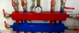
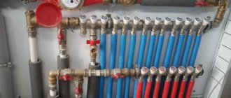
Collector distribution of water supply pipes in an apartment
Collector distribution of water supply pipes in an apartment differs from the standard system by the installation of a T-shaped distributor. The wiring diagram has many advantages, one of the important ones is adjusting the pressure so that it is the same along the entire length of the pipeline, making the process of repairing outdated sections easier.
Collector device - what is it? The collector device is a plumbing part that helps mix the water of two branches; from the collector, water flows to different points in the system. From the device, the water is divided into streams that have the same pressure. Thus, the manifold is considered to be a fluid distributing mechanism.
It is installed on the central riser pipe. Collector wiring involves installing a collector. The design of the collector is simple; you can install it yourself.
Selection of distribution manifold
The main rule is that the diameter of the collector should in no case be less than the size of the supply line pipe.
The larger the diameter of the distribution “comb”, the better for uniform pressure at the points of water and/or coolant collection. Incorrect selection of the “comb” (see recommendations above), for example, for a water supply system, can cause jumps in flow rate on different devices (see Fig. 2) and cause imbalance, for example, on a mixer.
Rice. 2. The result of incorrect selection of collectors for cold and hot water supply
If control valves are not installed at the apartment inlet of hot and cold water to forcibly stabilize the pressure in the “comb”, then for apartment collectors it is especially important to adhere to the rules of the connection sequence. It is necessary to connect devices, the uneven flow of which has little effect on the performance or comfort of the water supply, as “lower” as possible downstream of the water in the “comb”
The water heater should be connected first, then the faucets, then the washing machine and dishwasher (making sure that the “no water” shut-off valve is set to a pressure lower than the drop caused by the change in water supply), and at the very end of the manifold - the cistern drain pipe ( see Fig. 3).
Rice. 3 Example of connecting an apartment cold water distribution manifold
Which collector should I choose for my apartment’s water supply system?
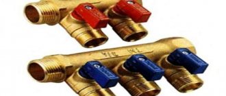
The manifolds manufactured by FAR have gained the greatest popularity in this area. High-quality collectors at very reasonable prices. Let's classify them as middle class. The line includes manifolds for a standard connection via a union nut and a Eurocone. There are also Russian-language inscriptions on the lambs, which is convenient.
If we consider all the best, then Oventrop is the most expensive.
The number of outlets on the collector must be equal to the number of water collection points.
For example, a standard one-room apartment in a new building, consumers:
- Kitchen (sink) hot water supply + hot water supply (hot + cold);
- HVS dishwasher;
- HVS toilet;
- DHW + cold water bath;
- DHW + cold water sink;
- HVS washing machine.
Such a scheme requires two collectors: 3 outlets for hot water supply and 5 outlets for cold water supply.
Solar collector savings opportunity
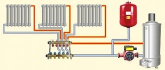
It is possible to connect several coolant heating sources to the heating circuit. Often solid fuel boilers operate in parallel with electric ones. this allows you to maintain the operating mode of the heating system at night or in the absence of owners for several days.
But this mode cannot be called economical - electricity is one of the most expensive resources. Modern developments make it possible to use solar energy to heat the coolant by installing a solar collector.
The solar collector is an installation that can be used all year round, even in cloudy temperatures. On sunny days it is most effective and heats up to the temperature of the boiler supply circuit - up to 70-90 degrees.
Homemade solar collector
A solar collector is a fairly simple device; it is not difficult to make it yourself. In terms of efficiency, a homemade solar water heater may be inferior to industrial models, but given their price - from 10 to 150 thousand rubles, a solar collector made by yourself will very quickly pay for itself.
To make it you need:
- a coil made of a metal tube, usually copper, you can take a suitable one from an old refrigerator;
- scraps of copper pipe with a 16 mm thread on one side;
- plugs and valves;
- pipes for connection to the collector unit;
- storage tank with a volume of 50 to 80 liters;
- wooden planks for making a frame;
- sheet of expanded polystyrene 30-40 mm thick;
- glass, you can take window glass;
- thick aluminum foil.
The coil is freed from freon residues by washing it with a stream of running water. A frame with a size slightly larger than a coil is made from a wooden lath or block. Holes are drilled in the lower part of the frame to remove the coil tubes.
On the reverse side, a sheet of polystyrene foam is attached to it with glue or self-tapping screws - this will be the bottom of the collector. This material has excellent thermal insulation characteristics, which will help reduce heat loss.
The top of the solar collector is covered with glass, securing it to glazing beads or slats. Pipes are attached to the ends of the coil for connection to the heating manifold unit. This can be done using adapters or flexible liners.
The collector is placed on the southern slope of the roof. The pipes lead to a storage tank equipped with an air valve, and from there to the heating distribution manifold.
Video: how to make your own solar heater
A manifold heating system is the most efficient way to connect different heaters to one or more heating sources. With its help, you can ensure stable temperature and comfort in the house, as well as uninterrupted and coordinated operation of all elements of the system.
Rules for installing heating systems
In heating systems, two collectors are used - supply and return. If the system is supposed to be balanced manually, control valves and balancing flow meters are connected to the supply manifold pipes, and shut-off valves are installed on the return side.
Theoretically, instead of control valves, you can use cheaper shut-off valves - with its help you can also change the amount of fluid flow. But in this case, it will quickly fail, since it is not designed for this mode of operation.
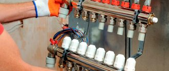
Collector heating system
If there is a thermostat in the heating system, instead of manual taps, fittings with servo drives are installed on the supply manifold. In this case, the coolant flow through each radiator will be adjusted automatically.
The supply manifold should be located higher than the return manifold. The pipes themselves can be laid any way you like.
If in a traditional radiator connection scheme the supply line must be higher than the return line, then in the collector line their location does not matter at all. Therefore, pipes are most often laid inside the floor.
Advantages of the scheme
Heating systems for a country house
The advantages of this coolant supply scheme are ease of use. Operation of the system and control of heating devices are as comfortable as possible:
- The temperature of each circuit element can be controlled centrally. Being near the collector, the homeowner can limit the supply of coolant to any register or turn it off completely. It is convenient to control the temperature in each room.
- Each branch that extends from the collector feeds only one radiator. Therefore, small-diameter pipes can be used to lay highways. In most cases, highways are laid in a concrete base. This heats up the floor.
- If necessary, using a collector it is easy to form several independent circuits with different temperature indicators. For this, it is preferable to use the so-called hydraulic arrow - a type of collector. It is distinguished by a large internal diameter of the pipe.
The installation of this version of collector heating is somewhat unusual. It is proposed to create short circuits between the hot water supply and the return lines.
The water heated by the boiler constantly circulates along the contours of the hydraulic arrow. In this case, the hot coolant can be collected at different distances from the collector, creating a temperature difference even in a single room. This option can be used for complex heating of a house - using traditional systems and “warm floors”.
Tee wiring
This scheme is a budget option for laying a water pipeline. It requires special skills and special tools for installation. This wiring can be observed in typical apartments from the times of construction of the USSR.
What is this design? This is the main pipe to which all cold water consumers are connected via tees. Exactly the same principle is used to install a hot water supply system.
With this method, the main pipe is a collector and must be larger in diameter than other branches.
Despite the simple design and installation, such a system still has disadvantages:
- When several equipment operates simultaneously in the system, the water pressure drops significantly.
- Temperature fluctuations may occur.
- There is no possibility of blocking a single water intake point.
- If any part malfunctions and while it is being repaired, it is necessary to completely shut off the water supply from the riser.
- Often, when several taps are opened at the same time, the water pressure drops significantly.
- This type of scheme is not suitable for apartments with a large area. The longer the main pipe, the less water the installed equipment will receive.
It is necessary to carefully consider the layout of pipes and tees. This will help save on repair work and use of the system.
It is important that the materials used are of high quality. This will help reduce the risk of malfunctions.
An example of selecting an apartment distribution manifold
Let's consider an example of selecting an apartment collector according to the connection diagram shown in Fig. 3, that is, to four water points. Table 2 regulates the required flow rate at 0.28 l/s. Let the water supply to the house be made of a 1/2″ steel pipe (DN = 15 mm), allowing a flow rate of 0.29 l/s at a flow speed of up to 1.5 m/s. The supply to the “comb” is made with a metal-polymer pipe 20×2.0 (3/4″). According to the manufacturer’s data, we determine that the permissible flow rate through such a pipe is 0.3 l/s, which exceeds the capacity of the house inlet (1/2″). Having chosen the VTc.500NE collector with a nominal diameter of 1″ (DN = 30 mm), we check the general recommendations for choosing collectors (see above).
The cross-sectional areas of the “comb” (see Table 3) and the inlet (1/2″) differ by a factor of 4. With this ratio of nominal diameters, the reduction in losses along the length of the “comb” (formula 1) will be 23 times. This is not ideal (the ratio of the diameters of the comb and the supply is not :1, but 2:1), but in this case it is not critical: if the connection order is observed (see Fig. 3), the distribution manifold for water supply with 4 outlets will be able to fulfill its balancing role in dynamic mode of operation.
Large range of distribution manifolds
Table 3 shows, as an example, different numbers of outputs designed for connecting floor and apartment water supply and heating systems. In addition to water supply, these systems are suitable for both radiator heating and low-temperature systems, for example, “warm floors” and heating of open areas.
Table 3. VALTEC manifolds and manifold blocks
Distribution manifolds made of stainless steel, for example, VTc.510.SS, are becoming especially popular. They are successfully used in floor distribution units of water heating systems of typical multi-apartment buildings.
Views: 4,713
Design and principle of operation
Redistribution of the water jet by the collector into several directions with the same pressure is the main function of the installation.
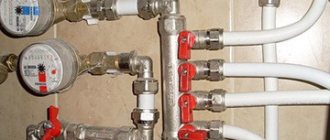
The switchgear is connected directly to the riser. There is a threaded connection on both sides (internal thread on one, external thread on the other) for connection to the main pipe and additional manifolds.
The inlet hole is 20-40 percent larger in size than the outlet holes. For a collector water supply system in a standard apartment, the first section is 3/4 inch, the second - 1/2 inch.
Shut-off elements at the outlet allow you to shut off the water flow in a timely manner and adjust the power for each individual point to stabilize pressure or save on water.
Manifolds without taps
It is not always necessary in a house or apartment to regulate the flow of water in the pipes running from the water distribution to the plumbing fixtures. Moreover, with a small number of devices, it is not necessary to be able to turn off these devices individually.
In this case, you can get away from collectors with control valves and use a simplified collector water supply scheme, using collectors without taps.
The main function of such collectors - equalizing pressure in the distribution water supply system - will remain the same, but monitoring tasks will no longer be required.
For example, you have a large number of water consumers in your apartment: a washing machine, a water heater, a toilet, a kitchen sink, a shower in the bathroom, a sink in the bathroom, a shower in the toilet. With this or more consumers, a series (tee) circuit may not be effective and the use of several devices may be difficult.
If the apartment (house) has normal water pressure, then the simplest distribution manifolds without taps can solve the problem of comfortable use. They are not suitable for underfloor heating systems, but will do an excellent job in plumbing and heating.
Advantages and disadvantages of the collector system
Separately, it should be noted the advantage of being able to connect consumers that are located at a remote distance from the riser. The presence of a valve on each outlet allows cutting off with lines, which is very convenient for repair and maintenance.
The advantages of collector wiring are considered:
- Constant water pressure and continuous supply in sufficient quantity.
- Ease of inspection to identify blockages and other pipeline faults.
- The minimum number of connections that are most susceptible to depressurization. There are no large number of tees, as in a series circuit, which is called tee wiring.
- The ability to locally shut off the pressure to carry out preventive and repair work when eliminating consumer breakdowns (washing machine, mixer, shower, bidet, bathtub, etc.). At the same time, you can use other instruments and devices.
To maintain the attractiveness of the interior, such wiring is hidden in a box with a hatch, through which the collector is serviced, the operating mode is monitored, and the outlets are closed. The remaining elements of the pipelines can be hidden in the walls or floor.
With all the advantages, there are also disadvantages:
- High price. More materials and fastening elements will be required. The number of pipes that will have to be spent during the installation process exceeds the minimum purchase volume, as is the case with a series connection.
- Difficult to install. It's not just about the work front. Already at the calculation stage, difficulties may arise. Of course, you can figure it out on your own, but hiring specialists is a clear advantage and a guarantee of the system’s effectiveness. True, the volume of work (as well as complexity) leads to an increase in the estimated cost.
But these shortcomings are covered by the fact that each outlet can be equipped with additional equipment necessary for the uninterrupted operation of equipment and plumbing fixtures. So, the check valve will save water in the boiler, the pressure switch will set the required mode, etc.
But all this will only work if the scheme is drawn up correctly. The manifold is connected to the riser (after the meter and the ball shut-off valve). A pipe leading to the consumer is connected to each outlet with a threaded connection. You can embed all the necessary additional equipment into it for efficient and safe operation.
Flaws
Despite the wide control possibilities, manifold heating distribution has not become widespread. And there are good reasons for this:
- Increased consumption of main pipes compared to conventional heating schemes. The more complex the building geometry, the more material needs to be purchased. Increased installation costs are also one of the significant reasons for low consumer demand.
- Traditional systems can be easily mounted on the wall in open or hidden versions. It is possible to lay a lot of lines from the comb only under the floor. Otherwise, you will get a very depressing picture, where heat mains will dominate the interior. And the material consumption for wall mounting will increase significantly.
- A prerequisite for installing the liner inside a concrete screed is the absence of joints. Each connection point is potentially dangerous from the point of view of breakthroughs. The prospect of destroying the foundation in order to eliminate a coolant leak looks depressing and requires a considerable investment of money, labor and time.
- The hydraulic resistance of a system with a mass of pipelines increases significantly. Especially if the diameter of the lines is small. Therefore, no gravity heating systems can even be considered. Only forced circulation of heated water.
- If you plan to use several independent heating circuits, then a circulation pump must be installed for each of them. Otherwise, the scheme simply will not work. Hence another item of additional costs.
- In any case, the system turns out to be energy-dependent, since it will not be able to function without a heating pump. Again, it’s a nuisance if for some reason there is no electricity. Or you will have to take care of an autonomous power supply.
All shortcomings ultimately come down to additional material costs. We can safely say that the collector wiring option cannot be classified as a budget solution.
Recommendations
- The highway routing scheme guarantees trouble-free operation. It is important to first develop a project and, based on it, calculate the required amount of material.
- The diagram should indicate the arrangement of all the necessary parts and elements, as well as routes with branches. This is necessary for the correct operation of the system.
- You should give preference only to high-quality products and do not skimp on purchasing expensive materials. Cheap parts, as a rule, are of poor quality; their use in any case will lead to an emergency, and therefore to the replacement of the entire water supply system.
To carry out installation work yourself, you must have experience in working with soldering and welding equipment. But if such skills are missing, then specialists can be called in to carry out such work.
General design principles
There is no uniform instruction for drawing up a detailed design of collector heating systems. In each individual case, heating devices and equipment are selected individually. But it will be useful for every interested person to familiarize himself with a few general tips.
The collector circuit is not for a city apartment.
An exception can be considered cases when builders in new houses additionally install one pair of valves in apartments, to which a heating circuit of any configuration can be connected. In this case, collector wiring is safely installed. With common risers for all apartments, a collector system is impossible.
Suppose there are several risers in the apartment and one or two heating devices are connected to each. You want a common collector circuit to be installed, and install a pair of combs on one riser with heat distribution throughout the apartment, disconnecting from all other risers. As a result, you will get a large difference in pressure and temperature of the “return” at your insertion. This will lead to the fact that the neighbors in the riser will have almost cold batteries in their apartments. As a result, a visit from a representative of the housing office is inevitable, who will draw up an act on illegal changes in the heating configuration and oblige you to make an expensive alteration of the heating system.
The system must be mounted so that the automatic air vent is located directly on the collectors. This is the best option, because sooner or later all the air in the circuit will pass through them.
The collector wiring system has many features, but some of them are also typical for other types of heating systems:
- The circuit must be equipped with an expansion tank, the volume of which must exceed 10% of the total coolant volume.
- The expansion tank is best placed in front of the circulation pump, on the “return”, in the direction of water movement. When using a hydraulic arrow, the circuit should be designed so that the tank is installed in front of the main pump, which circulates water in a small circuit.
- The choice of installation location for circulation pumps in each circuit is not important, but it is better to install them on the return flow. The operating temperature is lower here. The pump must be mounted so that the shaft is positioned strictly horizontally. Otherwise, at the first air bubble, the device will remain without lubrication and cooling.
Pipe selection
To determine which pipes are used to install the collector heating system, you need to understand the specifics of the collector wiring. Let's remember what can influence our choice:
- Pipes must be selected from those sold in coils. This allows you to avoid making connections in the wiring installed inside the screed.
- Pipes should not be afraid of corrosion and have a long service life. The reason is still the same: opening up the concrete floor to replace pipes is not part of our plans.
- The tensile strength and heat resistance of pipes is selected depending on the heating operating parameters. For radiators in a private house, the optimal parameters are 50 - 75°C water temperature and a pressure of 1.5 atm; for heated floors at the same pressure, 30 - 40°C is sufficient.
When a collector heating system is installed in apartment buildings, which is quite rare, the operating pressure should be 10 - 15 atm. at permissible water carrier temperature - 110 - 120°C. Based on these parameters, you have to make a choice of pipes.
It is necessary to install collector wiring when building a house. After laying the finished floor, installing this system will not be economically feasible, since the floors will have to be opened. Most often in this case, open wiring of heating systems is used.
Features and purpose
The manifold, also called a comb, in its simplest form is a piece of pipe with several pipes cut into it.
In pipeline systems, this element plays the role of a central distributor - devices or small sequences of them are connected to the pipes through pipes.
Such schemes are called collector or beam.
The main task of the collector is to ensure a uniform flow of medium to the devices and make the operation of each of them independent of the flow rate on other devices.
Different collectors may differ from each other in the following ways:
- Availability of additional equipment: manifolds are produced with shut-off and control valves, gearboxes, pressure gauges and even circulation pumps already installed on their pipes. The most modern modifications are equipped with sensors and automatic valves.
- Material: today both metal collectors (brass, steel, bronze and copper) and plastic (polypropylene) are used. Cheap silumin products (their unusually low weight gives them away) are not worth purchasing due to their low strength and fragility.
- Number of outlets (nozzles): usually collectors have 2 - 4 nozzles. But this should not limit the user: if necessary, several collectors can be combined into one, increasing the number of taps to the desired value.
- Maximum permissible pressure.
- Bandwidth.
- Center distance between branches.
Additional equipment is made from various materials. The quality of the collector and the maximum temperature of the working environment depend on their choice.
Collector wiring
If you connect the equipment using a manifold circuit, this will ensure good water pressure at all distribution points. This system is excellent for connecting a large type of plumbing equipment, therefore it is actively used in apartments with a large area and in various rooms.
Advantages of a collector circuit.
- If, for example, the shower breaks down, the ability to use the faucet in the kitchen is still preserved.
- Resistance to water hammer.
- The pressure remains normal even when plumbing is connected at the same time.
- Ability to quickly detect leaks.
Disadvantages of collector water supply wiring:
- Unaesthetic appearance.
- High price category.
- Difficulties arising during installation work.