The efficiency of its further operation and service life depend on how correctly the piping of a solid fuel boiler is done. In operation, wood and coal heat generators differ from units using other types of fuel, and therefore require a special approach.
It is proposed to consider in detail how, after installing the heating wiring, to connect a solid fuel boiler, including with your own hands. A description of various schemes for connecting a TT boiler to a heating system can be found in this material.
What is the difference between solid fuel boilers
In addition to burning various types of solid fuel, heat generators have a number of differences from other heat sources. These features should be taken for granted and always taken into account when connecting a solid fuel boiler to a water heating system. What are they:
- High inertia. At the moment, there are no ways to quickly extinguish a solid fuel fire in a combustion chamber.
- Formation of condensation in the firebox during heating. The peculiarity is manifested due to the flow of coolant with a low temperature (below 50 ° C) into the boiler tank.
Note. The phenomenon of inertia is absent only in one type of solid fuel units - pellet boilers. They have a burner into which wood pellets are fed in doses; after the supply is stopped, the flame goes out almost immediately.
Diagram of the design of a direct combustion TT boiler with forced air injection.
Inertia creates the danger of overheating the water jacket of the heater, as a result of which the coolant in it boils. Steam is generated, which creates high pressure, rupturing the body of the unit and part of the supply pipeline. As a result, there is a lot of water in the furnace room, a lot of steam and a solid fuel boiler unsuitable for further use.
A similar situation can arise when the heat generator piping is done incorrectly. After all, in fact, the normal operating mode of wood-burning boilers is maximum; it is at this time that the unit reaches its rated efficiency. When the thermostat reacts to the coolant reaching a temperature of 85 °C and closes the air damper, combustion and smoldering in the firebox still continues. The water temperature rises another 2-4 °C, or even more, before its growth stops.
In order to avoid excess pressure and a subsequent accident, an important element is always involved in the piping of a solid fuel boiler - a safety group, which will be discussed in more detail below.
Another unpleasant feature of the unit operating on wood is the appearance of condensation on the inner walls of the firebox due to the passage of not yet heated coolant through the water jacket. This condensate is not God’s dew at all, since it is an aggressive liquid that quickly corrodes the steel walls of the combustion chamber. Then, having mixed with the ash, the condensate turns into a sticky substance that is not so easy to tear off from the surface. The problem is solved by installing a mixing unit in the piping circuit of a solid fuel boiler.
This coating serves as a heat insulator and reduces the efficiency of a solid fuel boiler.
It is too early to breathe a sigh of relief for owners of heat generators with cast iron heat exchangers that are not afraid of corrosion. Another misfortune may await them - the possibility of destruction of cast iron from temperature shock. Imagine that in a private house the electricity was turned off for 20-30 minutes and the circulation pump driving water through the solid fuel boiler stopped. During this time, the water in the radiators has time to cool down, and in the heat exchanger it has time to heat up (due to the same inertia).
Electricity appears, the pump turns on and directs the cooled coolant from the closed heating system into the heated boiler. Due to a sharp temperature change, the heat exchanger experiences a temperature shock, the cast iron section cracks, and water runs onto the floor. It is very difficult to repair; it is not always possible to replace a section. So even in this situation, the mixing unit will prevent an accident, which will be discussed below.
Emergency situations and their consequences are described not with the aim of scaring users of solid fuel boilers or encouraging them to purchase unnecessary elements of piping schemes. The description is based on practical experience, which must always be taken into account. If the heating unit is connected correctly, the likelihood of such consequences is extremely low, almost the same as with heat generators using other types of fuel.
Features of piping circulation pumps
Pump piping
The pump in the heating system is necessary for stable circulation of the coolant, which would not depend on the degree of expansion of the water. It is installed according to the scheme at the point with the lowest water temperature - before it enters for reheating into the boiler.
The piping of the circulation pump of the heating system consists of two parallel heating circuits. This is necessary to ensure the smooth flow of hot water during a power outage. If this is not done, the resistance from the fixed impeller will worsen the already unsatisfactory performance of natural circulation.
In practice, the following components must be included in the piping of the heating system circulation pump:
- Shut-off valves. With its help, the flow of water into a certain section of the main line is blocked - main or auxiliary;
- Mesh filter. Necessary to protect the impeller and pump rotor from rust particles or sediment from the surface of the pipes. It is a mandatory component in the piping of the heating system pump, installed in front of it in the direction of the coolant flow;
- Check valve on auxiliary line. With natural circulation, the phenomenon of changing the direction of movement of hot water is possible. To prevent this, be sure to install a check valve in the heating pump piping.
These are the main components of the circulation pump piping in heating systems. If you need to install an additional one, you should purchase a synchronizer for stable operation of the pumps. It will synchronize the rotation speed of the impellers, thereby minimizing the possibility of water hammer and periodic pressure changes in the heating system.
How to connect a solid fuel boiler
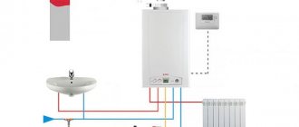
The canonical connection diagram for a solid fuel boiler contains two main elements that allow it to function reliably in the heating system of a private home. This is a safety group and a mixing unit based on a three-way valve with a thermal head and a temperature sensor, shown in the figure:
The always open output of the mixing valve (the left pipe in the diagram) must be directed to the pump and heat generator, otherwise there will be no circulation in the small boiler circuit
Note. The expansion tank is not shown here - it must be connected to the return line of the heating system in front of the pump (in the direction of water flow).
The presented diagram shows how to connect the unit correctly and is used with any solid fuel boilers, including pellet ones. You can find various general heating schemes - with a heat accumulator, an indirect heating boiler or a hydraulic arrow, in which this unit is not shown, but it must be there. The method of protecting against moisture loss in the firebox is discussed in detail in the video:
The task of the safety group, installed directly at the outlet of the supply pipe of a solid fuel boiler, is to automatically relieve pressure in the network when it rises above a set value (usually 3 Bar). This is done by a safety valve, and in addition to it, the element is equipped with an automatic air vent and a pressure gauge. The first releases the air appearing in the coolant, the second serves to control the pressure.
Attention! The installation of any shut-off valves is not allowed on the section of the pipeline between the safety group and the boiler. If you installed a ball valve to cut off and repair group parts, remove the handle from the stem.
How the scheme works
The mixing unit, which protects the heat generator from condensation and temperature changes, operates according to the following algorithm, starting from kindling:
- The firewood is just starting to burn, the pump is on, the valve on the side of the heating system is closed. The coolant circulates in a small circle through the bypass.
- When the temperature in the return pipeline rises to 50-55 °C, where the attached remote-type sensor is located, the thermal head, at its command, begins to press the three-way valve stem.
- The valve slowly opens and cold water gradually enters the boiler, mixing with hot water from the bypass.
- As all the radiators warm up, the overall temperature increases and then the valve closes the bypass completely, passing all the coolant through the heat exchanger of the unit.
An important nuance. Paired with a 3-way valve, a special head with a sensor and capillary is installed, designed to regulate the water temperature in a certain range (for example, 40...70 or 50...80 degrees). A regular radiator thermal head will not work.
This piping scheme is the simplest and most reliable; you can easily install it yourself and thus ensure the safe operation of the solid fuel boiler. There are a couple of recommendations regarding this, especially when piping a wood-burning heater in a private house with polypropylene or other polymer pipes:
- Make the section of the pipe from the boiler to the safety group from metal, and then lay plastic.
- Thick-walled polypropylene conducts heat poorly, which is why the surface-mounted sensor will openly lie, and the three-way valve will lag. For correct operation of the unit, the area between the pump and the heat generator, where the copper flask is located, must also be metal.
Connecting with copper pipes will not protect polypropylene from destruction in the event of overheating of the TT boiler.
But it will allow the temperature sensor and safety valve on the safety group to work correctly. Another point is the installation location of the circulation pump. It is best for him to stand where he is shown in the diagram - on the return line in front of the wood-burning boiler. In general, you can install the pump on the supply side, but remember what was said above: in an emergency, steam may appear in the supply pipe.
The pump is unable to pump gases, so when the chamber is filled with steam, the impeller will stop and the coolant circulation will stop. This will speed up a possible explosion of the boiler, because it will not be cooled by water flowing from the return.
Way to reduce the cost of strapping
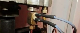
The condensate protection circuit can be reduced in cost by installing a three-way mixing valve of a simplified design that does not require connecting an overhead temperature sensor and thermal head. It already has a thermostatic element installed, set to a fixed mixture temperature of 55 or 60 °C, as shown in the figure:
Special 3-way valve for solid fuel heating units HERZ-Teplomix
Note. Similar valves, which maintain a fixed temperature of mixed water at the outlet and are intended for installation in the primary circuit of a solid fuel boiler, are produced by many well-known brands - Herz Armaturen, Danfoss, Regulus and others.
Installing such an element definitely allows you to save on piping the TT boiler. But in this case, the possibility of changing the temperature of the coolant using a thermal head is lost, and its deviation at the output can reach 1-2 °C. In most cases, these shortcomings are insignificant.
Normative base
A heating boiler operating on solid fuel is subject to increased safety requirements. Equipment installation standards are given in SNiP II-35-76 Boiler installations (current edition SP 89.13330.2011).
According to the standard, hot water solid fuel boilers for public, administrative and residential buildings with a water heating temperature at the outlet of up to 115 °C can be placed in built-in and attached boiler rooms (placement on the roof is not allowed). In multi-apartment residential buildings they can only be installed in attached premises. Heating equipment must be factory-made, with built-in automation.
The maximum total thermal power of solid fuel boilers for a built-in boiler room should not exceed 1.5 MW. For an attached room this figure is not limited.
Requirements for the design of a chimney for the removal of combustion products, the installation of ventilation and water heating are regulated by the standard SP 31-106-2002 Design and construction of engineering systems of single-apartment residential buildings. It also stipulates the conditions for correct installation of the device (distance from the walls, boiler room finishing material), they must be taken into account together with the boiler operating manual.
Trim option with buffer tank
The presence of a buffer tank is extremely desirable for the operation of a boiler using solid fuels and here’s why. In order for the unit to function efficiently and produce heat with the efficiency declared in the passport (from 75 to 85% for different types), it must operate at maximum mode. When the air damper is closed to slow down combustion, there is a lack of oxygen in the firebox and the efficiency of wood burning decreases. At the same time, emissions of carbon monoxide (CO) into the atmosphere increase.
For reference. It is because of emissions that in most European countries it is prohibited to operate solid fuel boilers without a buffer tank.
On the other hand, at maximum combustion, the temperature of the coolant in modern heat generators reaches 85 ° C, and one load of firewood lasts only 4 hours. This does not suit many owners of private houses. The solution to the problem is to install a buffer tank and connect it to the TT boiler piping so that it serves as a storage tank. Schematically it looks like this:
By measuring the temperatures T1 and T2, you can configure the layer-by-layer loading of the container with a balancing valve
When the firebox is burning with all its might, the buffer tank accumulates heat (in technical language, it is loaded), and after extinguishing it releases it into the heating system. To control the temperature of the coolant supplied to the radiators, a three-way mixing valve and a second pump are also installed on the other side of the storage tank. Now it is not at all necessary to run to the boiler every 4 hours, because after the firebox goes out, the heating of the house will be provided for some time by the buffer tank. How long depends on its volume and heating temperature.
Reference. Based on practical experience, the capacity of a heat accumulator can be determined as follows: for a private house with an area of 200 m², you will need a tank with a volume of at least 1 m³.
There are a couple of important nuances. In order for the piping circuit to work safely, you need a solid fuel boiler whose power is sufficient for simultaneous heating and loading of the buffer tank. This means that power will be required 2 times higher than the calculated one. Another point is to select the pump performance so that the flow rate in the boiler circuit is slightly higher than the amount of water flowing in the heating circuit.
An interesting option for connecting a TT boiler with a homemade buffer tank (aka an indirect heating boiler) without a pump was demonstrated by our expert in the video:
Circuit with heat accumulator
A number of European Union countries have introduced rules according to which schemes for connecting solid fuel boilers to the heating system must necessarily include a heat accumulator. Without it, the operation of such heaters is simply prohibited. The reason is the high content of carbon monoxide (CO) in emissions while limiting the supply of oxygen to the firebox to reduce the intensity of combustion.
With normal air access, harmless carbon dioxide (CO2) is formed, so the firebox must operate at full capacity, transferring energy to the heat accumulator. Then the CO content will not exceed environmental standards. In the post-Soviet space there are no such requirements yet; accordingly, we continue to block the air supply in order to achieve slow smoldering of wood, for example, in a long-burning boiler.
Heat accumulators are commercially available as a finished product, although many craftsmen make them themselves. By and large, this is a tank covered with a layer of thermal insulation. The factory version may have a built-in DHW circuit and heating element for heating water. This solution allows you to accumulate heat from a wood-burning boiler, and when it is idle, provide heating for the house for some time. The connection diagram of the boiler with the heat accumulator is shown in the figure:
Note. In the circuit, instead of a mixing unit consisting of several elements, a ready-made device is installed that performs the same functions - LADDOMAT 21.
Joint connection of two boilers
To increase the heating comfort of a private home, many owners install two or more heat sources that run on different energy sources. At the moment, the most relevant combinations of boilers are:
- natural gas and wood;
- solid fuel and electricity.
Accordingly, the gas and solid fuel boiler must be connected in such a way that the second automatically replaces the first after burning the next portion of firewood. The same requirements are put forward for connecting an electric boiler to a wood boiler. This is quite simple to do when a buffer tank is involved in the piping scheme, since it simultaneously plays the role of a hydraulic arrow, as shown in the figure.
The boiler supply lines are connected to the upper pipes of the heat accumulator, the return pipes to the lower ones
Advice. Information on calculating the volume of the buffer tank can be found in a separate publication.
As you can see, thanks to the presence of an intermediate storage tank, 2 different boilers can serve several heating distribution circuits at once - radiators and heated floors, and in addition load an indirect heating boiler. But not everyone installs a heat accumulator with a TT boiler, since this is not a cheap pleasure. In this case, there is a simple diagram, and you can install it yourself:
The circuit takes into account the peculiarity of the electric boiler - the built-in circulation pump always works
Note. The scheme is valid for both electric and gas heat generators operating together with solid fuel.
Here the main source of heat is a wood heater. After a stack of firewood burns out, the air temperature in the house begins to drop, which is registered by the room thermostat sensor and immediately turns on heating by the electric boiler. Without a new load of firewood, the temperature in the supply pipe decreases and the overhead mechanical thermostat turns off the pump of the solid fuel unit. If you ignite it after some time, everything will happen in the reverse order. This video is described in detail about this joint connection method:
Two-pipe system with top wiring
In a two-pipe heating system with overhead wiring, the expansion tank is placed at the highest point.
This two-pipe scheme is very similar to the previous one, only here it is provided for the installation of an expansion tank in the very top part of the system, for example, in an insulated attic or under the ceiling. From there, the coolant goes down to the radiators, gives them part of its heat, and then is sent through the return pipe to the heating boiler.
Why is such a scheme needed? It is optimal in multi-storey buildings with a large number of radiators. Thanks to this, more uniform heating is achieved, and there is no need to install a large number of air vents - the air will be removed through the expansion tank or through a separate bleeder that is part of the safety group.
Advantages and disadvantages of a two-pipe system with top wiring
There are a lot of positive features:
- it is possible to heat multi-storey buildings;
- saving on air vents;
- you can create a system with natural coolant circulation.
There are also some disadvantages:
Using vertical wiring will lead to additional difficulties when installing hidden heating.
- pipes are visible everywhere - this scheme is not suitable for interiors with expensive finishing, where elements of heating systems are usually hidden;
- in tall buildings it is necessary to resort to forced circulation of the coolant.
Despite the disadvantages, the scheme remains quite popular and widespread.
Features of installation of two-pipe systems with top wiring
This scheme eliminates the need to locate the heating boiler at the lowest point. Immediately after the boiler, the supply pipe is diverted upward, and an expansion tank is installed at the highest point. Coolant is supplied to the radiators from above, so a lateral or diagonal radiator connection scheme is used here. After this, the cooled coolant is sent to the return pipe.
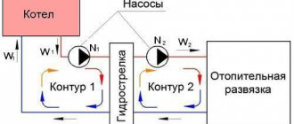
Tying using the method of primary and secondary rings
There is another way to combine a solid fuel boiler with an electric one to supply a large number of consumers. This is a method of primary and secondary circulation rings, which provides for hydraulic separation of flows, but without the use of a hydraulic needle. Also, for reliable operation of the system, a minimum of electronics is required, and a controller is not needed at all, despite the apparent complexity of the circuit:
The trick is that all consumers and boilers are connected to one primary circulation ring by both the supply and return pipelines. Due to the small distance between connections (up to 300 mm), the pressure drop is minimal compared to the pressure of the main circuit pump. Due to this, the movement of water in the primary ring does not depend on the operation of the secondary ring pumps. Only the temperature of the coolant changes.
Theoretically, any number of heat sources and secondary rings can be included in the main circuit. The main thing is to choose the right pipe diameters and the performance of the pumping units. The actual performance of the main ring pump must exceed the flow rate in the most “gluttonous” secondary circuit.
To achieve this, it is necessary to perform a hydraulic calculation and only then will it be possible to select the right pumps, so an ordinary homeowner cannot do without the help of specialists. In addition, it is necessary to link the operation of solid fuel and electric boilers by installing shut-off thermostats, as described in the following video:
Recommendations for arranging the circuit
Let's take a closer look at the application of this heating scheme for a 2-story house.
On the ground floor: kitchen, dining room, toilet, bathroom. On the second: three bedrooms. We use a primary and secondary ring system. It is advisable to design the boiler room in the basement of the house. We decide on the boiler power: a heat generator with a capacity of 25 kW is suitable for such a house. Selects the type of boiler: pellet or pyrolysis, it doesn’t matter whether both will work. Here the fuel decides which fuel is best to buy, and we install that unit.
We install the system sequentially:
- install a heat generator;
- We mount a closed primary ring nearby;
- we cut the main circulation pump into the primary ring;
- We connect the fuel unit to the primary ring with pipes from the boiler and to it, the distance between the connected pipes is no more than 300 mm;
- we install pipes for heating underfloor heating on the 2nd floor for 3 rooms: three entrances and three exits;
- we cut in consumers on the first floor - everything is also parallel;
- connect the expansion tank;
- install a faucet to fill the system with water;
- For each heating circuit we install its own pump on the return pipeline;
- all secondary circuit pumps must be connected to temperature sensors, which will regulate the supply of coolant individually to each branch, and, if necessary, turn off the pump.
The use of a primary-secondary system will allow:
- create the necessary microclimate in the house at minimal cost and maximum use of equipment;
- use the heating system most efficiently;
- avoid the passage of water through idle units (that is, increase the efficiency of the system as a whole);
- quickly and easily carry out repair work on system elements.
Single-circuit and double-circuit heating boiler.
A single-circuit boiler has a fairly simple operating principle. During installation, it is connected to the chimney. For the normal functioning of the system, the presence of normal natural draft is sufficient.
Often, single-circuit boilers are installed, which in their design have an open combustion chamber, which requires the creation of certain conditions in the room.
During its operation, the boiler uses air from the room. That is why it should be installed in a separate room. It is worth noting that when a single-circuit boiler operates, substances and gases harmful to the human body accumulate, this is the main reason for the need to equip a room with a boiler with a chimney or hood. If all the above conditions are created, the risk of explosion will be eliminated and will also ensure the safe use of the equipment.
A double-circuit heating boiler differs from a single-circuit analogue in its universal purpose: it maintains the degree of coolant in the heating circuit and heats water for domestic needs. Single-circuit generators can also indirectly heat water. The heat transfer process is carried out during the passage of the coolant through the secondary heat exchanger.
The main difference between a double-circuit boiler and a single-circuit boiler is the direct transfer of thermal energy to water. The main feature is that when hot water is consumed, the coolant is not subject to heating, and parallel operation of two circuits is excluded. Practice shows that the operating mode of the boiler is not important for houses with high-quality thermal insulation, it follows that with thermal inertia, the heating circuit will be the same for any type of heating. An impressive volume of hot water can be obtained by combining a single-circuit design and heating columns.
A double-circuit boiler should not be designed in combination with a natural circulation system, since after heating of the coolant stops, the movement of the liquid quickly stops. The secondary heating process takes quite a long time, and the heat in the radiator is distributed unevenly.
The main advantage of the scheme is the ability to operate in natural circulation mode. The booster of the collector in this case is a pipe through which the coolant moves to the upper filling.
What does the heating boiler piping consist of?
Knowing what the boiler piping should do, we can easily guess what is included in its composition and select the appropriate equipment. Such equipment is located directly next to the boiler (on the walls and floor of the boiler room) and on it:
1 - filter; 2 - circulation pump; 3 - ball valves; 4 - expansion tank; 5 - boiler; 6 — pressure gauge; 7 — air vent; 8 - safety valve; 9 - system refill-drain unit
Let's look at the piping, starting with the return line.
1. The coolant approaches the circulation pump and enters the filter:
- which stands in front of (!) the pump.
2. The pump, as can be seen from the diagram, is located in front of the boiler. There are ball valves on both sides of the pump so that you can change the pump or clean the filter without draining the coolant from the entire system. Replacing the pump is quite simple, since it is secured with union nuts.
In general, the main requirement when installing a boiler is to provide fairly easy access to the pump and other piping elements.
3. There is an expansion tank between the pump and the boiler. The expansion tank can be installed anywhere in the system, but it is preferable as shown in the diagram.
4. Then the coolant enters the boiler, heats up and enters the supply pipe.
5. At the boiler outlet, a safety group is required: automatic air vent + safety valve + pressure gauge. The boiler may also have a thermometer to monitor the temperature in the boiler.
6. A ball valve with a fitting on which you can attach a hose and feed the system from the water supply. Or drain the coolant from the system.
The above are mandatory elements that must be included in the boiler piping.
The wall-mounted boiler has all the same devices, only they are already inside the housing.
If you are not familiar with any of the listed equipment, you can find complete information about it in the section on heating equipment.
Other connection diagrams for a solid fuel heater
We connect the device to the main line with admixture
The design of the heating system in this case includes the following elements:
- heating equipment safety group (thermostatic valve, safety valve);
- expansion tank (heat accumulator);
- a circulation pump that supplies coolant to the entire system;
- shut-off valves.
This scheme is different in that it has an additional mixing circuit and taps, with the help of which you can easily volume the coolant in the mixing circuit. This type of connection allows you to keep heating radiators at a comfortable temperature, despite the fact that the heating boiler operates in optimal mode.
For example: in a pyrolysis boiler the water temperature is 70-80 0C, the heating system for living rooms produces a coolant temperature for the batteries of no more than 65 0C.
Connecting a solid fuel unit with a hydraulic boom
This type of connection is used in situations where the heating system has more than one circuit. The hydraulic distributor or hydraulic arrow performs the task of a fuse, excluding the hydraulic action of the circulation pumps installed on each circuit. The hydraulic arrow simultaneously acts as a sludge catcher and degasses the entire heating complex.
The connection diagram for a solid fuel boiler with a hydraulic boom in a house consists of the following elements:
- control devices;
- expansion tank;
- two circulation pumps independent from each other;
- hydraulic boom;
- heating radiators;
- distribution combs (dirt collectors).
*
Basic requirements for the boiler room
Domestic solid fuel heat generators are installed in separate dry rooms, outbuildings or separate buildings. The dimensions of the boiler room are determined by the dimensions of the unit, as well as the features of its maintenance, however, the smallest allowable area is 7 square meters. In this case, it is necessary to provide a place protected from atmospheric influences for storing the fuel supply - it must be dry before loading.
3D diagram of a heating system with a solid fuel boiler
If the walls of the boiler room are made of flammable materials, they must be covered with a 2.5-3 cm layer of plaster or thermal insulation in the form of an 8 mm layer of asbestos and sheet iron. If there is no fire protection for the ceiling, the distance from it to the boiler body must be at least 120 cm.
The normal operation of a solid fuel boiler is ensured by a stable air flow. Therefore, it is necessary to provide supply and exhaust ventilation in the boiler room. The first channel, measuring 30x30 cm, should go to the bottom of the wall opposite the chimney, and the exhaust hole, whose dimensions should be 40x40 cm, should be located no more than 40 cm from the ceiling. The boiler room ventilation must ensure normal draft. If there is a shortage of it, the boiler’s performance drops, and if there is an excess, it becomes difficult to regulate the fuel combustion process.
Supply and exhaust ventilation and smoke removal in the boiler room
The solid fuel boiler must be installed on a strictly horizontal fireproof (concrete or brick) platform about 7 cm thick. On a wooden floor, such equipment can only be installed with an intermediate brick layer covered with a 3-4 mm metal sheet or at least 5 cm cement screed . The base of a solid fuel boiler should be 10-20 cm wider than the external dimensions of the body, but the sides of the firebox should be additionally equipped with a safety zone at least 40 cm wide.