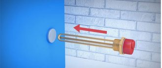
A four-way mixing valve means a fragment of a heating system with four connected pipes, inside of which a coolant fluid with different temperatures circulates. Designed to prevent overheating of a solid fuel heating boiler. Due to the thermostatic valve, the temperature range inside the heating equipment does not exceed 110°C. At 95°C, it opens the cold water supply and cools the system to the desired state.
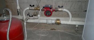
Four-way valve with manual control Source feniks-trade.ru
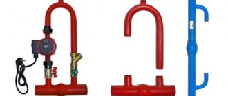
Manufacturers
Four-way valves for heating are produced by companies such as Honeywell, ESBE, VALTEC and others.
Today it is a manufacturer that is included in the list of 100 leading global companies compiled by Fortune magazine.
Honeywell 4 way valve
Four-way valves Honeywell V5442A series are manufactured for systems where the coolant is water or liquids with a glycol percentage of up to 50. They are designed to operate at temperatures from 2 to 110 ° C and at operating pressures up to 6 bar.
Honeywell manufactures valves with connection sizes of 20, 25, 32 mm. Therefore, the Kvs coefficient values range from 4 to 16 m³/h. The series devices operate together with electric drives. For systems with higher power, the flanged series of valves ZR-FA is used.
The Honeywell four-way valve will not cause any difficulties during installation; there are many implementation options.
All its products are economical, reliable and convenient to use in heating, cooling and water supply systems.
ESBE offers a 4-way heating valve with internal thread. The valve body is made of brass. Working pressure 10 atmospheres, temperature 110 degrees (short-term - 130 degrees). The four-way mixing valve is produced in sizes 1/2-2″, with a capacity of 2.5 -40 Kvs.
Valtek offers mixing valves for various purposes, which are designed for durable operation in the engineering system (water heated floor, built-in wall, ceiling heating and cooling, hot water supply). The manufacturer's products can be found anywhere in Russia and the CIS countries.
It cannot be said that a four-way valve for heating will not require financial investment. Installing the device will be expensive, however, on the other hand, the operational efficiency and, as a result, profitability, justifies the monetary costs. There is only the main condition - the presence of a high-quality electrical network, since without it the valve drive will stop working.
This allows for somewhat automated control, but does not make it possible to constantly maintain a certain temperature at the inlet to the boiler (which is necessary for the safety and durability of the heat generator). Indeed, with large temperature differences, there is a possibility of condensation forming with subsequent corrosion of the heat exchanger, and the intensity of scale formation also increases. If a cast iron heat exchanger is used, cracks may appear in sections of the heat exchanger. In addition, the stress at the connections of boiler parts increases, primarily at the joints and along the welds.
Therefore, for operational safety and durability of the equipment, as well as to achieve the required level of comfort, four-way valves are used to separate the heating and boiler circuits. In Fig. Figure 2 shows a typical diagram using a solid fuel boiler and a hot water storage tank (one outlet from the boiler, after which the coolant is distributed to hot water heating and the heating system). The separation of the boiler circuit and the heating system circuit is carried out using a 4-way valve, which allows for constant circulation in the boiler circuit and, at the same time, in the heating system circuit.
Rice. 2. Installation diagram of a solid fuel boiler to a heating system with forced circulation of coolant and a 4-way valve: 1 - boiler; 2 — automatic boiler control unit; 3 — coolant temperature sensor; 4 - room thermostat; 5 - circulation pump; 6 – heat consumer; 7 - differential valve; 8 - four-way mixing valve; 9 — expansion tank; 10 - hot water boiler; 11 - boiler pump; 12 — shut-off valves; 13 - filter
At the same time, in addition to the extreme positions, in the middle position 50% of the coolant goes into the heating system, mixing with 50% of the coolant returning from the heating system, and the remaining part returns back to the boiler, mixing with the rest of the coolant from the heating system. It is also possible to maintain, in contrast to regulation with 3-way valves, a flow separation constant in other strictly defined proportions. For example, 30% of the coolant is in the boiler circuit, 70% is in the heating system. Or any other ratio (Fig. 3).
Rice. 3. 4-way valve positions
Such constancy of consumption is very important for a solid fuel boiler, since, as we noted above, when using it there are not such wide opportunities to influence the intensity of the combustion process as in gas boilers. The use of an automatic draft regulator allows you to regulate the temperature only at the outlet of the boiler, but not on the return line
Device and functions
The four-way heating valve rotates the spindle in the housing itself. Rotation must be carried out freely, because the bushing does not contain threads. The functioning part of the spindle has a pair of recesses, with the help of which the flow through two passages is opened.
As a consequence, the flow is regulated and is unable to pass directly to the second sample. The flow can turn into any pipe that is located on the left or right side of it. It turns out that all the flows that pass from different directions are mixed and dispersed through four pipes.
There are devices where a pressure rod functions instead of a spindle, but such designs are not intended to mix flows.
A four-way valve for heating is an element of a heating system to which four pipes are connected, having a coolant of different temperatures. Inside the housing there is a sleeve and a spindle. The latter has to work with a difficult configuration.
The operation of a 4-way mixer can be controlled as follows:
p, blockquote 6,0,0,0,0 —>
- Manual. In this case, to distribute the flows, it is necessary to install the rod in one specific position. And this position must be adjusted manually.
- Automatic (with thermostat). Here, an external sensor gives a command to the spindle, as a result of which the latter begins to rotate. Because of this, the heating system maintains a stable specified temperature.
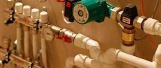
Installation diagram of a four-way mixing valve in a heating system
The main functions of the 4-way valve are as follows.
p, blockquote 7,0,0,0,0 —>
- Mixing water flows with different heating temperatures. The device is used to prevent overheating of a solid fuel boiler. The four-way mixing valve does not allow the temperature in the boiler equipment to rise above 110 °C. When heated to 95 °C, the device starts cold water to cool the system.
- Protection of boiler equipment. The 4-way valve prevents the formation of corrosion and thereby extends the service life of the entire system.
Thanks to the 4-way heating valve, a uniform flow of hot and cold coolant is achieved. For normal operation, no bypass installation is required, since the valve itself allows the required volume of liquid to pass through. The device is used where temperature regulation is required. First of all, in the heating system with radiators in conjunction with a solid fuel boiler. If in other cases the fluid is adjusted using a hydraulic pump and bypass, then in this case the operation of the valve completely replaces these devices. It turns out that the boiler functions stably and constantly receives a certain volume of coolant.
Heating with four-way valve
Installation of a heating system with a four-way valve:
The connection diagram for a heating system with a four-way mixer consists of the following elements:
- Boiler;
- Four-way thermostatic mixer;
- Safety valve;
- Pressure reducing valve;
- Filter;
- Ball valve;
- Pump;
- Heating batteries.
The installed heating system must be flushed with water. This is necessary so that various mechanical particles are removed from it. After this, the operation of the boiler must be checked under a pressure of 2 bar and with the expansion tank turned off.
Please note that a short period of time must pass between the start of full operation of the boiler and its testing under hydraulic pressure. The time limit is due to the fact that if there is no water in the heating system for a long time, it will be susceptible to corrosion.
A four-way valve is an element of the heating system to which four pipes having coolants of different temperatures are connected, and is used to prevent overheating of a solid fuel boiler. The thermostatic valve prevents the temperature inside the boiler from exceeding 110 °C. Already at a temperature of 95 °C it starts cold water to cool the system.
Four way valve design
The body is made of brass, 4 connecting pipes are attached to it. Inside the body there is a sleeve and a spindle, the operation of which has a complex configuration.
The thermostatic mixing valve performs the following functions:
- Mixing water flows of different temperatures. Thanks to mixing, there is a smooth regulation of water heating;
- Boiler protection. The four-way mixer prevents corrosion, thereby extending the life of the equipment.
Four-way mixer diagram
The operating principle of such a heating valve is to rotate the spindle inside the housing. Moreover, this rotation must be free, since the sleeve does not have a thread. The working part of the spindle has two openings through which the flow opens in two passes. Thus, the flow will be throttled and will not be able to pass directly to the second sample. The flow will be able to turn into any of the nozzles located on the left or right side of it. So, all flows coming from opposite sides are mixed and distributed over four pipes.
There are designs in which a pressure rod works instead of a spindle, but such devices cannot mix flows.
Valve operation is controlled in two ways:
- Manual. Flow distribution requires the rod to be installed in one specific position. This position must be adjusted manually.
- Auto. The spindle rotates as a result of a command received from an external sensor. Thus, the heating system constantly maintains the set temperature.
The four-way mixing valve ensures a stable flow of cold and hot coolant. The principle of its operation does not require the installation of a differential bypass, because the valve itself allows the required amount of water to pass through. The device is used where temperature control is necessary. First of all, this is a radiator heating system with a solid fuel boiler. If in other cases the coolant is regulated using a hydraulic pump and bypass, here the operation of the valve completely replaces these two elements. As a result, the boiler operates in a stable mode, constantly receiving a dosed amount of coolant.
Heating with four-way valve
Installation of a heating system with a four-way valve:
The connection diagram for a heating system with a four-way mixer consists of the following elements:
- Boiler;
- Four-way thermostatic mixer;
- Safety valve;
- Pressure reducing valve;
- Filter;
- Ball valve;
- Pump;
- Heating batteries.
The installed heating system must be flushed with water. This is necessary so that various mechanical particles are removed from it. After this, the operation of the boiler must be checked under a pressure of 2 bar and with the expansion tank turned off.
Please note that a short period of time must pass between the start of full operation of the boiler and its testing under hydraulic pressure. The time limit is due to the fact that if there is no water in the heating system for a long time, it will be susceptible to corrosion.
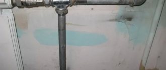
How to make a heating system with a four-way valve
Heating system assembly
The heating system is assembled in the following order:
- A pump is fixed to the return pipe, which is responsible for the circulation rate of the coolant fluid.
- Safety branches are mounted on the inlet and outlet pipes. It is prohibited to install a valve and tap on the latter, due to the high pressure under which they will be exposed.
- A check valve is installed on the water supply pipeline. Its functions will include protecting the system from the negative effects of backpressures and siphon drainages.
- The expansion tank is located at the highest point of the pipeline. This condition is necessary to reduce the likelihood of circulation problems resulting from water expansion. It can be installed in both horizontal and vertical positions.
- Installation of expansion valve. This is accomplished by installing a thermostatic valve with a double sensor. It is needed to achieve uniform distribution of thermal energy. As already mentioned, when the water temperature rises above 95°C, it transmits a pulse signal to the thermostatic mixer, which opens the cold flow. After the system has cooled down, another signal is given, the valve closes, and the water supply stops.
- The assembly is completed by installing the pressure reducer. It is installed directly next to the inlet pipe of the thermostatic mixer. Designed to reduce the pressure drop when opening the valve and supplying liquid.
Morphological analysis of the word four-way
FOUR WAY
- inanimate
FOUR WAY
- animate
Basic form of the word:
FOUR WAY
All word forms with grammatical information:
| Word | Information |
| FOUR WAY | singular, nominative, masculine, inanimate, animate |
| FOUR WAY | accusative, singular, masculine, inanimate |
| FOUR WAY | singular, feminine, inanimate, animate, genitive |
| FOUR WAY | dative, singular, feminine, inanimate, animate |
| FOUR WAY | singular, feminine, inanimate, animate, instrumental |
| FOUR WAY | singular, feminine, inanimate, animate, prepositional |
| FOUR WAY | singular, masculine, inanimate, animate, genitive |
| FOUR WAY | accusative, singular, masculine, animate |
| FOUR WAY | singular, inanimate, animate, genitive, neuter |
| FOUR WAY | dative, singular, masculine, inanimate, animate |
| FOUR WAY | dative, singular, inanimate, animate, neuter |
| FOUR WAY | singular, masculine, inanimate, animate, instrumental |
| FOUR WAY | singular, inanimate, animate, neuter, instrumental |
| FOUR WAY | dative, plural, inanimate, animate |
| FOUR WAY | singular, masculine, inanimate, animate, prepositional |
| FOUR WAY | singular, inanimate, animate, prepositional, neuter |
| FOUR WAY | singular, feminine, nominative, inanimate, animate |
| FOUR WAY | accusative, singular, feminine, inanimate, animate |
| FOUR WAY | singular, feminine, inanimate, animate, instrumental |
| FOUR WAY | singular, nominative, inanimate, animate, neuter |
| FOUR WAY | accusative, singular, inanimate, animate, neuter |
| FOUR WAY | nominative, plural, inanimate, animate |
| FOUR WAY | accusative, plural, inanimate |
| FOUR WAY | plural, inanimate, animate, genitive |
| FOUR WAY | accusative, plural, animate |
| FOUR WAY | plural, inanimate, animate, prepositional |
| FOUR WAY | plural, inanimate, animate, instrumental |
| FOUR WAYS | inanimate, animate, comparative degree (for adjectives) |
| FOUR MOVES | inanimate, animate, comparative degree (for adjectives) |
| FOUR WAYS MORE | second genitive or second prepositional case, inanimate, animate, comparative degree (for adjectives) |
| FOUR MOVES | second genitive or second prepositional case, inanimate, animate, comparative degree (for adjectives) |
Popular manufacturers
There are many manufacturers of three-way valves on the domestic market. The choice of one model or another depends, first of all, on:
- type of mechanism (and let us remember, it can be mechanical or electrical);
- areas of use (DHW, cold water, “warm floor”, heating).
Esbe is rightfully considered the most popular device.
- a Swedish valve from a company that has been around for over a hundred years. This is a reliable, high-quality and durable product that has proven itself in many areas. A combination of European quality and modern technology.
Another popular model is the American Honeywell - a true brainchild of high technology. Simple operation, convenience and comfort, compactness and reliability - these are the distinctive features of these valves.
Finally, relatively “young” but promising devices are valves from the Valtec line - the result of joint cooperation between engineers from Italy and Russia. All products are of high quality and are sold with a seven-year warranty. They differ in that they have a very affordable price.
Wiring diagram for a four-way reverse osmosis valve
- home
- Scheme
- Osmosis circuit RO-6 with pump and 4-way
CONNECTION DIAGRAM, OPERATING PRINCIPLE OF REVERSE OSMOSIS
The website provides schematic diagrams of typical reverse osmosis systems, which differ slightly from each other. Each reverse osmosis diagram may contain partial descriptions of parts and components that need to be familiarized with for further understanding of how reverse osmosis works. More details HERE
How reverse osmosis works
Tap water through a (reducer), tee and supply valve enters a mechanical 5 micron cartridge, on which dirt, rust, small suspensions and other sediments are removed.
The water then flows to a carbon cartridge, where 98% of chlorine, organics and chemicals are removed. The next stage of cleaning is a mechanical 1 micron cartridge or another carbon cartridge (The choice of cartridge depends on the concentration of chlorine in the water; if there is no chlorine in the water, then it is quite possible to install mechanical cartridges made of polypropylene fiber everywhere. First of all, this applies to wells and wells, because a carbon cartridge is necessary so that the membrane does not oxidize from chlorine and the pores do not increase in diameter. If the used cartridges are covered with mucus (bacterial colonies), this means that there is no chlorine in the water, then the carbon can be replaced with mechanics, for better and longer filtration of the membrane.) All three of these cartridges are called pre-filters, since they affect the service life of the membrane, and very little affect the taste of the water. When buying cartridges for pre-cleaning, many make the mistake of thinking that if the osmosis cartridge is expensive, then the water will be better. The water then passes through the main reverse osmosis filter, a membrane that removes 95-99% of soluble contaminants from the water. The membrane divides the input water into two streams: Pure water or permeate. Dirty water - concentrate Dirty water flows through the flow limiter, which creates pressure on the membrane, and through the drain clamp into the sewer. Clean water accumulates very slowly in the tank through a 4-way valve. When you open the faucet at the sink, water under the pressure of the tank bulb quickly flows through reverse osmosis post-filters: carbon cartridge, mineralizer or bioceramics. This is where the pleasant taste of water is formed, the gases that the membrane allows through are removed, and minerals are added, if necessary. And the acidity level is adjusted if the mineralizer has such a function. Mineralizers and bioceramic cartridges can be installed on both single and double taps. If you installed on a double tap, then you must constantly use all taps. We can explain to you the detailed problem of choosing a faucet if you contact us. We recommend installing AP-GAC AquaPlus post-charcoal, which effectively removes gases because it is made from finely ground natural activated carbon (for a larger contact area with water). This can be confirmed by the coal dust that comes out as a black stream when installing a new cartridge. We also recommend installing the AP-MIN AquaPlus mineralizer, which effectively saturates the water with minerals and adjusts the pH level. This can be confirmed by testing the total salt content and acidity level of the water. But we do not recommend using cartridges in bacteriologically contaminated water, since bacteria, multiplying in the form of mucus, cover the post-filter granules with a thin layer and the cartridges stop effectively filtering and saturating the water a few weeks after installation. For better filtration of post-cartridges, we recommend disinfecting the reverse osmosis system.
Valves classification
Without lengthy introductions, we note that the device can be of two types according to the principle of operation. It could be:
- dividing;
- mixing.
The features of each type of action are clear from their names. The mixing device consists of two outputs and an input. In other words, it is necessary to mix fluid flows, which may be required in order to reduce its temperature. By the way, this is the most optimal option for setting the desired mode in the “warm floor”.
The procedure for adjusting the temperature regime is extremely simple. You just need to know about the current temperature indicators of the incoming liquid flows, accurately calculate the required proportions of each of them so as to obtain the required indicators at the output. By the way, this device, subject to proper installation and adjustment, can also function for flow separation.
But the separating valve divides one flow in two, therefore, it is equipped with one inlet and two outlets. This device is used primarily to separate the flow of hot water in hot water systems. Although quite often it is found in the piping of air heaters.
Externally, both options are almost identical. But if you look at their cross-sectional drawing, their main difference is immediately visible. The rod, which is installed in a mixing-type device, has one ball valve. It is located in the center and blocks the main passage.
As for separating devices, the stem has two such valves, which are installed at the outlets. They function according to the following principle: one of them is pressed against the saddle, closing the passage, and the other, in parallel, opens passage No. 2.
According to the control method, modern models can be:
- electrical;
- manual.
In most cases, a manual device is used, which in appearance resembles an ordinary ball valve, but is equipped with three outlet pipes. But electric models with automatic control are used mainly in private homes, namely to distribute heat. For example, the user can set the temperature regime by room, and the working fluid will flow in accordance with the distance of the room from the heating device. As an option, you can combine it with a “warm floor”.
Video - Device in a boiler group
Three-way valves, as well as other devices, are determined in accordance with the pressure in the system and the diameter of the inlet. All this is regulated by GOST. And if the requirements of the latter are not met, this will be regarded as a gross violation, especially when it comes to the pressure indicator in the line.
About the operating principle of the valve
Like its more “modest” three-way brother, the four-way valve is made of high-quality brass, but instead of three connecting pipes it has as many as 4. Inside the body, a spindle with a cylindrical working part of a complex configuration rotates on a sealing sleeve.
It has selections in the form of flats on two opposite sides, so that in the middle the working part resembles a damper. It retains a cylindrical shape at the top and bottom to allow compaction.
The spindle with the bushing is pressed to the body with a cover with 4 screws; an adjustment handle is attached to the end of the shaft from the outside or a servo drive is installed. The detailed diagram of a four-way valve shown below will help you visualize what this whole mechanism looks like:
The spindle rotates freely in the sleeve because it has no thread. But at the same time, samples made in the working part can open the flow through two passages in pairs or allow three flows to mix in different proportions. How this happens is shown in the diagram:
For reference. There is another design of a four-way valve, where instead of a rotating spindle, a pressure rod is used. But such elements cannot mix flows, but only redistribute. They have found their application in gas double-circuit boilers, switching the flow of hot water from the heating system to the DHW network.
The peculiarity of our functional element is that the coolant flow supplied to one of its nozzles can never pass to the other outlet in a straight line. The flow will always turn into the right or left pipe, but will never flow into the opposite one. At a certain position of the spindle, the damper allows the coolant to pass immediately to the right and left, mixing with the flow coming from the opposite inlet. This is the principle of operation of a four-way valve in a heating system.
Tadiran air conditioner repair. Replacing a four-way valve in a Tadiran air conditioner
Let's consider replacing a four-way valve in a Tadiran air conditioner, as well as the possibility of adapting a used four-way valve from another air conditioner. According to tradition, we install the external air conditioner unit on the stand and check the parameters. If the valve is faulty, the following problems are identified:
The air conditioner does not switch to heating mode,
The air conditioner does not switch to cooling mode,
· the compressor runs, but nothing happens (no heating, no cooling on any of the radiators). In this case, most often there is a strong hissing in the external unit.
In this case, it does not switch to heating mode. We disassemble the external unit and pump out the old freon into a used freon cylinder.
Next, I suggest simply cutting off the tubes going to the four-way valve with side cutters. The old valve has been removed. Next, I propose to figure out why we are installing a used valve and not a new one. The valve has a simple device and it is not difficult or expensive to purchase, but installation will take a lot of time. Inside the valve, the moving element is a rod made of plastic, and the connecting tubes are no more than 5 cm long, so during soldering, the valve must be cooled, otherwise the rod will melt and the valve will fail. In addition, the solder seams are inverted and soldering occurs upside down, and for this it is necessary to unsolder all the tubes and the compressor, i.e. unsolder and solder back the entire air conditioner. I am against unnecessary soldering operations, since this leads to the formation of scale inside the tubes, and scale is washed out only under the conditions of the manufacturer. We try on a used valve with tubes at the installation site, I was lucky - the valve turned out to be complete with a service suction port, we can use it. We are planning three solder seams.
Next, I cut the tubes to size and a suitable pipe from below, pass through with a pipe expander of the appropriate size. Next, we perform soldering with an oxygen torch and solder containing silver. The photo shows the compressor discharge tube. We also bend, expand and solder the suction tube of the compressor.
The inlet pipe of the condenser (radiator of the external unit) is soldered directly into the tee without expansion, and is pre-bent. A very important point - the pipes should not touch each other, as well as the housing and the compressor; to do this, bend them or even fasten them with ties through a rubber shock absorber.
We assemble the housing, connect the stand pipes, vacuum it, fill it with freon and check the operation of the entire external unit. https://www.youtube.com/watch?v=SGmvIKLB9I8
The operating parameters of the external unit in heating and cooling mode are not ideal, but close to it. Let's summarize the work - disassembly, three solder seams and four
Repairman's Guide
| 52. Four way cycle reversal solenoid valve |
During the oil crisis of 1973, the demand for the installation of large numbers of heat pumps increased sharply. Most heat pumps are equipped with a four-way reversal solenoid valve, used to either set the pump to summer mode (cooling) or to cool the outdoor battery in winter mode (heating). The subject of this section is to examine the operation of the four-way cycle reversal solenoid valve (V4V) found on most classic air-to-air heat pumps and cycle reversal defrost systems (see Figure 60.14) to effectively control the direction of movement. streams. A) V4V Operation Let's study the diagram (see Fig. 52.1) of one of these valves, consisting of a large four-way main valve and a small three-way control valve mounted on the main valve body. At the moment we are interested in the main four-way valve. First, we note that of the four fittings of the main valve, three are located next to each other (and the compressor suction line is always connected to the middle of these three fittings), and the fourth fitting is located on the other side of the valve (the compressor discharge line is connected to it). Note also that on some V4V models the suction fitting may be offset from the center of the valve. 'T\ However, the discharge (item 1) and suction (item 2) lines of the compressor are ALWAYS connected as indicated in the diagram in Fig. Inside the main valve, communication between the various channels is ensured using a movable spool (item 3), sliding together with two pistons (item 4). A small hole is drilled in each piston (item 5) and, in addition, each piston is equipped with a needle (item 6). Finally, 3 capillaries (item 7) are cut into the main valve body in the places shown in Fig. 52.1, which are connected to the solenoid valve control, if you do not thoroughly study the principle of operation of the valve. Each element we present plays its role in V4V operation. That is, if one of these elements fails, it could be the cause of a very difficult to detect fault. Now let's look at how the main valve works... If the V4V is not mounted on the installation, you will expect an audible click when you apply voltage to the solenoid valve, but the spool will not move. Indeed, in order for the spool inside the main valve to move, it is absolutely necessary to provide a pressure difference across it. Why this is so, we will now see. The discharge Pnag and suction Pvsas lines of the compressor are always connected to the main valve as shown in the diagram {Fig. 52.2). At this point, we will simulate the operation of a three-way control solenoid valve using two manual valves: one closed (item 5) and the other open (item 6). In the center of the main valve, Pnag develops forces that act on both pistons equally: one pushes the spool to the left (item 1), the other to the right (item 2), as a result of which both of these forces are mutually balanced. Recall that both pistons have small holes drilled into them. Therefore, Pnag can pass through the hole in the left piston, and Pnag will also be installed in the cavity (position 3) behind the left piston, which pushes the spool to the right. Of course, at the same time Rnag penetrates through the hole in the right piston into the cavity behind it (item 4). However, since valve 6 is open, and the diameter of the capillary connecting the cavity (item 4) with the suction line is much larger than the diameter of the hole in the piston, gas molecules passing through the hole will instantly be sucked into the suction line. Therefore, the pressure in the cavity behind the right piston (item 4) will be equal to the pressure Рвсас in the suction line. Thus, a more powerful force caused by the action of Pnag will be directed from left to right and will force the spool to move to the right, communicating the non-pressure line with the left fitting (pos. 7), and the suction line with the right fitting (pos. 8). If now Pnag is directed into the cavity behind the right piston (close valve 6), and Pvsac into the cavity behind the left piston (open valve 5), then the predominant force will be directed from right to left and the spool will move to the left (see Fig. 52.3). At the same time, it connects the discharge line with the right fitting (pos. 8), and the suction line with the left fitting (pos. 7), that is, exactly the opposite compared to the previous option. Of course, the use of two manual valves for reversibility of the operating cycle cannot be provided. Therefore, we will now begin to study the three-way control solenoid valve, which is most suitable for automating the cycle reversal process. We have seen that movement of the spool is only possible if there is a difference between the values of Pnag and Pvsac. The three-way control valve is designed only to relieve pressure from either one or the other supply cavity of the main valve pistons. Therefore, the control solenoid valve will have a very small size and remains the same for any diameter of the main valve. The central inlet of this valve is a common outlet and is connected to the suction cavity {see. rice. 52.4). If voltage is not applied to the winding, the right input is closed, and the left one is connected to the suction cavity. And vice versa, when voltage is applied to the winding, the right input is connected to the suction cavity, and the left one is closed. Let us now study the simplest refrigeration circuit equipped with a four-way valve V4V (see Fig. 52.5). The solenoid winding of the control solenoid valve is not energized and its left input connects the cavity of the main valve, behind the left spool piston, with the suction line (remember that the diameter of the hole in the piston is much smaller than the diameter of the capillary connecting the suction line to the main valve). Therefore, in the cavity of the main valve, to the left of the left piston of the spool, a Pvsas is installed. Since Pnag is installed to the right of the spool, under the influence of the pressure difference the spool moves sharply inside the main valve to the left. Having reached the left stop, the piston needle (pos. A) closes the hole in the capillary connecting the left cavity with the Pvsac cavity, thereby preventing the passage of gas, since this is no longer necessary. In fact, the presence of a constant leak between the cavities Pnag and Pvsac can only have a harmful effect on the operation of the compressor. Note that the pressure in the left cavity of the main valve again reaches the value Pnag, but since Pnag has also established in the right cavity, the spool will no longer be able to change your position. Now let us carefully remember the location of the condenser and evaporator, as well as the direction of flow in the capillary expansion device. Before you continue reading, try to imagine what will happen if voltage is applied to the solenoid valve winding. When power is applied to the solenoid valve winding, the right cavity of the main valve communicates with the suction line and the spool moves sharply to the right. Having reached the stop, the piston needle interrupts the outflow of gas into the suction line, blocking the opening of the capillary connecting the right cavity of the main valve with the suction cavity. As a result of the movement of the spool, the discharge line is now directed to the former evaporator, which has become a condenser. Likewise, the former condenser has become an evaporator and the suction line is now connected to it. Note that the refrigerant in this case moves through the capillary in the opposite direction (see Fig. 52.6). To avoid mistakes in the names of heat exchangers, which alternate between being an evaporator and a condenser, it is best to call them an external battery (a heat exchanger located outside the room) and an internal battery (a heat exchanger located indoors). B) Danger of water hammer During normal operation, the condenser is filled with liquid. However, we saw that at the moment of cycle reversal, the condenser almost instantly becomes an evaporator. That is, at this moment there is a danger of a large amount of liquid entering the compressor, even if the expansion valve is completely closed. To avoid such a danger, it is usually necessary to install a liquid separator on the suction line of the compressor. The liquid separator is designed in such a way that in the event of an influx of liquid at the outlet of the main valve, mainly during cycle reversal, it is prevented from entering the compressor. The liquid remains at the bottom of the separator, while pressure is taken into the suction line at its top point, which completely eliminates the risk of liquid entering the compressor. However, we have seen that oil (and therefore liquid) must constantly return to the compressor through the suction line. To give the oil this opportunity, a calibrated hole (sometimes a capillary) is provided at the bottom of the suction pipe... When liquid (oil or refrigerant) is retained at the bottom of the liquid separator, it is sucked through the calibrated hole, slowly and gradually returning to the compressor in such quantities that are insufficient to lead to undesirable consequences. B) Possible malfunctions One of the most difficult malfunctions of the V4 V valve is associated with the situation when the spool gets stuck in the intermediate position (see Fig. 52.8). At this moment, all four channels communicate with each other, which leads to a more or less complete, depending on the position of the spool when jammed, bypass of gas from the discharge line into the suction cavity, which is accompanied by the appearance of all signs of a malfunction such as “the compressor is too weak”: a decrease in - boat productivity, drop in condensation pressure, increase in boiling pressure (see section 22. “Compressor too weak”). Such jamming can occur accidentally and is due to the design of the main valve itself. In fact, since the spool is free to move inside the valve, it can move and, instead of being at one of the stops, remain in an intermediate position as a result of vibrations or mechanical shocks (for example, after transportation).
If the V4V valve has not yet been installed and therefore can be handled, the installer MUST check the position of the spool by looking inside the valve through the 3 lower holes (see Fig. 52.9). In this way, he can very easily ensure the normal position of the spool, since after the valve is soldered, it will be too late to look inside! If the spool is positioned incorrectly (Fig. 52.9, right), it can be brought to the desired state by tapping one end of the valve on a wooden block or piece of rubber (see Fig. 52.10). Never knock the valve against a metal part, as this risks damaging the valve tip or completely destroying it. Using this very simple technique, you can, for example, set the V4V valve spool to the cooling position (the discharge line communicates with the outdoor heat exchanger) when replacing a faulty V4V with a new one in a reversible air conditioner (if this happens in the middle of summer). The reason for the spool jamming in the intermediate position can also be numerous defects in the design of the main valve or auxiliary solenoid valve. For example, if the main valve body has been damaged by impact and has become deformed in the cylindrical part, such deformation will prevent the spool from moving freely. One or more capillaries connecting the cavities of the main valve with the low-pressure part of the circuit may become clogged or bent, which will lead to a decrease in their flow area and will not allow for a sufficiently rapid release of pressure in the cavities behind the spool pistons, thereby disrupting its normal operation (let us also recall times that the diameter of these capillaries must be significantly larger than the diameter of the holes drilled in each of the pistons). Signs of excessive burnout on the valve body and poor appearance of solder joints are an objective indicator of the qualifications of the installer who performed the soldering using a gas torch. Indeed, during soldering, it is imperative to protect the main valve body from heat by wrapping it with a wet rag or moistened asbestos paper, since the pistons and spool are equipped with sealing nylon (fluoroplastic) rings, which at the same time improve the sliding of the spool inside the valve. When soldering, if the temperature of nylon exceeds 100°C, it loses its sealing abilities and anti-friction characteristics, the gasket receives irreparable damage, which greatly increases the likelihood of the spool jamming during the first attempt to switch the valve. Let us recall that the rapid movement of the spool during cycle rotation occurs under the influence of the difference between Pnag and Pvsac. Consequently, movement of the spool becomes impossible if this difference AP is too small (usually its minimum permissible value is about 1 bar). Thus, if the control solenoid valve is activated when the AP differential is insufficient (for example, when starting a compressor), the spool will not be able to move freely and there is a danger of it getting stuck in an intermediate position. Sticking of the spool can also occur due to malfunctions in the control solenoid valve, for example, due to insufficient supply voltage or improper installation of the solenoid mechanism. Note that dents on the electromagnet core (due to impacts) or its deformation (during disassembly or as a result of a fall) do not allow the core sleeve to slide normally, which can also lead to valve jamming. It is worth recalling that the condition of the refrigeration circuit must be absolutely impeccable. In fact, if in a conventional refrigeration circuit the presence of copper particles, traces of solder or flux is extremely undesirable, then even more so for a circuit with a four-way valve. They can jam it or clog the holes in the pistons and capillary channels of the V4V valve. Therefore, before you begin dismantling or assembling such a circuit, try to think through the maximum precautions that you must take. Finally, we emphasize that it is strongly recommended that the V4V valve be mounted in a horizontal position to avoid even a slight drop of the spool under its own weight, as this can cause constant leaks through the upper piston needle when the spool is in the up position. Possible causes of spool jamming are shown in Fig. 52.11. Now the question arises. What to do if the spool is stuck? Before requiring the V4V valve to operate normally, the repairman must first ensure the conditions for this operation on the circuit side. For example, a lack of refrigerant in the circuit, causing a drop in both Pnag and Pvsac, can lead to a weak drop in the DR, insufficient for the free and complete transfer of the spool. If the appearance of the V4V (no dents, signs of impacts and overheating) seems satisfactory and there is confidence that there are no electrical faults (very often such faults are attributed to the V4V valve, while we are talking only about electrical defects), the repairman should ask the following question: Which heat exchanger? (internal or external) should the compressor discharge line be suitable and in what position (right or left) should the spool be located for a given operating mode of the installation (heating or cooling) and its design (heating or cooling with the control solenoid valve de-energized)? When the repairman has confidently determined the required normal position of the spool (right or left), he can try to put it in place, lightly but firmly, tapping the main valve body on the side where the spool should be located with a mallet or a wooden hammer (if there is no mallet, Never use a regular hammer or sledgehammer without first using a wooden spacer on the valve, otherwise you risk serious damage to the valve body (see Figure 52.12). In the example in Fig. 52.12 a hammer blow from the right forces the spool to move to the right (unfortunately, designers, as a rule, do not leave space around the main valve for striking!). Indeed, the compressor discharge pipe must be very hot (beware of burns, as in some cases its temperature can reach 100°C). The suction pipe is usually cold. Therefore, if the spool is moved to the right, fitting 1 should have a temperature close to the temperature of the discharge pipe, or, if the spool is moved to the left, close to the temperature of the suction pipe. We have seen that a small amount of gas from the discharge line (hence very hot) passes during the short period of time, when the spool is thrown, through two capillaries, one of which connects the cavity of the main valve on the side where the spool is located, with one of the inputs of the solenoid valve, and the other connects the output of the control solenoid valve to the suction line of the compressor. Further, the passage of gases stops, since the piston needle, which has reached the stop, blocks the opening of the capillary and prevents gases from entering it. Therefore, the normal temperature of the capillaries (which can be touched with your fingertips), as well as the temperature of the control solenoid valve body, should be almost the same as the temperature of the main valve body. If palpation gives different results, there is nothing left to do but try to figure them out. Let's say that during regular maintenance, a repairman notices a slight increase in suction pressure and a slight drop in discharge pressure. Since the lower left fitting is hot, it concludes that the spool is on the right. Feeling the capillaries, he notices that the right capillary, as well as the capillary connecting the output of the solenoid valve to the suction line, have an increased temperature. Based on this, he can conclude that there is a constant leak between the discharge and suction cavities and, therefore, the needle of the right piston does not provide a tight seal (see Fig. 52.14). He decides to increase the discharge pressure (for example, by covering part of the condenser with cardboard) in order to increase the pressure difference and thereby try to press the spool against the right stop. He then moves the spool to the left to ensure proper operation of the V4V valve, after which he returns the spool to its original position (increasing the discharge pressure if the pressure difference is insufficient, and checking the V4V response to the operation of the control solenoid valve). Thus, based on these experiments, he can draw the appropriate conclusions (in the event that the leakage flow continues to remain significant, it will be necessary to consider replacing the main valve). The discharge pressure is very low and the suction pressure is abnormally high. Since all four V4V valve connections are quite hot, the repairman concludes that the spool is stuck in the intermediate position. Feeling the capillaries shows the repairman that all 3 capillaries are hot, therefore the cause of the malfunction lies in the control valve, in which both flow sections were open at the same time. In this case, you should completely check all components of the control valve (mechanical installation of the electromagnet, electrical circuits, supply voltage, current consumption, condition of the electromagnet core) and try repeatedly, turning the valve on and off, to return it to operating condition, removing possible foreign particles from under one or both of its seats (if the defect persists, the control valve will need to be replaced). Regarding the control valve solenoid coil (and any solenoid valve coils in general), some novice repairmen would like some guidance on how to determine whether the coil is working or not. In fact, in order for the coil to excite a magnetic field, it is not enough to apply voltage to it, since a wire break may occur inside the coil. Some installers install the tip of a screwdriver on the mounting screw of the coil in order to assess the strength of the magnetic field (however, this is not always possible), others remove the coil and monitor the core of the electromagnet, listening to the characteristic knocking sound that accompanies its movement, and still others, having removed the coil, insert it into the hole for core with a screwdriver to ensure that it retracts under the force of the magnetic field. Let's take this opportunity to make a small clarification... As an example, consider a classic solenoid valve coil with a rating of -^| the nominal supply voltage is 220 V. As a rule, the developer allows a long-term increase in voltage relative to the nominal value by no more than 10% (that is, about 240 volts), without the risk of excessive overheating of the winding and guarantees normal operation of the coil with a long-term voltage drop of no more than, than 15% (that is, 190 volts). These permissible limits for the deviation of the electromagnet supply voltage are easily explained. If the supply voltage is too high, the winding becomes very hot and may burn out. Conversely, at low voltage, the magnetic field turns out to be too weak and will not allow retraction of the core together with the valve stem into the coil (see section 55. “Various electrical equipment problems”). If the supply voltage provided for our coil is 220 V, and the rated power is 10 W, we can assume that it will consume a current I = P / U, that is, 1 = 10 / 220 = 0.045 Ar (or 45 mA). Voltage applied I = 0.08 A A, Strong danger of coil burnout In fact, the coil will consume a current of about 0.08 A (80 mA), since for alternating current P = U x I x coscp, and for electromagnet coils coscp , as a rule, is close to 0.5. If the core is removed from an energized coil, the current consumption will increase to 0.233 A (that is, almost 3 times more than the rated value). Since the heat released during the passage of current is proportional to the square of the current, this means that the coil will heat up 9 times more than under nominal conditions, which greatly increases the danger of its combustion. If a metal screwdriver is inserted into an energized coil, the magnetic field will pull it inward and the current consumption will drop slightly (in this example to 0.16 A, that is, twice the nominal value, see Fig. 52.16). Remember that you should never remove an energized solenoid coil, as it can burn out very quickly. A good way to determine the integrity of the winding and check for the presence of supply voltage is to use a current clamp (transformer clamp), which is opened and moved towards the coil to detect the magnetic field created by it during normal operation. If the coil is energized, the ammeter needle deflects the transformer clamp, reacting as intended to a change in the magnetic flux near the coil allows, in the event of a malfunction, to register a sufficiently high current value on the ammeter (which, however, means absolutely nothing), which quickly gives confidence in the serviceability of the electrical circuits of the electromagnet. Note that the use of open transformer current clamps is permissible for any windings powered by alternating current (electromagnets, transformers, motors...), at a time when the winding being tested is not in close proximity to another source of magnetic radiation.
| 52.1. Examples of using |
Exercise #1 A repairman must replace the V4 V valve in the dead of winter on the installation shown in Fig. 52.18. After draining the unit of refrigerant and removing the faulty V4V, the repairman is asked the following question: Keeping in mind that the outside and inside temperatures are low, the heat pump must operate in heating mode for the conditioned space. Before installing the new V4V, what position should the spool be in: on the right, on the left, or does its position not matter? As a hint, here is a diagram engraved on the solenoid valve body. Solution to Exercise No. 1 Upon completion of the repair, the heat pump will have to operate in heating mode. This means that the internal heat exchanger will be used as a condenser (see Fig. 52.22). Studying the pipelines shows us that the V4V spool should be on the left. Therefore, before installing a new valve, the installer must ensure that the spool is actually on the left. He can do this by looking inside the main valve through the three lower connecting fittings. If necessary, move the spool to the left, either by tapping the left end of the main valve on a wooden surface, or by lightly hitting the left end with a mallet. Rice. 52.22. Only then can the V4V valve be installed in the circuit (paying attention to preventing excessive overheating of the main valve body during soldering). Now let's look at the symbols on the diagram, which is sometimes applied to the surface of the solenoid valve (see Fig. 52.23). Unfortunately, such diagrams are not always available, although their availability is very useful for V4V repair and maintenance. So, the spool was moved to the left by the repairman, and it is better that there is no voltage on the solenoid valve at the time of start-up. This precaution will allow you to avoid an attempt to reverse the cycle at the moment the compressor starts, when the difference in AP between pH is very small. It must be borne in mind that any attempt to reverse the cycle at a low differential AP is fraught with the danger of the spool jamming in an intermediate position. In our example, to eliminate such a danger, it is enough to disconnect the solenoid valve winding from the network when starting the heat pump. This will make it completely impossible to attempt to reverse the cycle when the AP differential is weak (for example, due to incorrect electrical installation). Thus, the listed precautions should allow the repairman to avoid possible malfunctions in the operation of the V4V unit when replacing it.
Let's study the diagram (see Figure 52.1) of one of these valves, consisting of a large four-way main valve and a small three-way control valve mounted on the main valve body. At the moment we are interested in the main four-way valve. First, we note that of the four fittings of the main valve, three are located next to each other (and the compressor suction line is always connected to the middle of these three fittings), and the fourth fitting is located on the other side of the valve (the compressor discharge line is connected to it). Note also that on some V4V models the suction fitting may be offset from the center of the valve. 'T\ However, the discharge (item 1) and suction (item 2) lines of the compressor are ALWAYS connected as indicated in the diagram in Fig. 52.1. Inside the main valve, communication between the various passages is ensured by a movable spool (item 3) sliding along with two pistons (item 4). A small hole is drilled in each piston (item 5) and, in addition, each piston is equipped with a needle (item 6). Finally, 3 capillaries (item 7) are cut into the main valve body in the places shown in Fig. 52.1, which are connected to the control solenoid valve. Rice. 52.1. danger if you do not thoroughly study the principle of operation of the valve. Each element we present plays its role in V4V operation. That is, if at least one of these elements fails, it may be the cause of a very difficult to detect fault. Let's now look at how the main valve works...
How it works
The three-way valve is installed in those sections of the pipelines where it is necessary to divide the flow of circulating fluid into 2 circuits:
- with variable hydraulic mode;
- with constant.
In most cases, a constant flow is required by those who are supplied with liquid of high quality and in designated volumes. It is regulated in accordance with quality indicators. As for the variable flow, it is used for objects where quality indicators are not the main ones. The quantity coefficient is of great importance there. Simply put, the coolant is supplied there according to the required quantity.
Note! Shut-off valves also include an analogue of the device described in the article - a two-way valve. How is it different? The fact is that the three-way option works on a completely different principle
The rod included in its design is unable to block the flow of liquid, which has constant hydraulic parameters.
The rod is open all the time, it is adjusted to a particular volume of liquid. Consequently, users will be able to get the volume they need, both in terms of quantity and quality. In general, this device is unable to stop the flow of fluid to a network in which the hydraulic flow is constant. In this case, it may well block a flow of variable type, due to which, in fact, the possibility of adjusting the flow/pressure arises.
And if you connect a pair of two-way devices, you can get one, but three-way. But it is necessary that both work in reverse, in other words, when one valve closes, the next one must open.
Practical use
Wherever it is necessary to ensure high-quality regulation of the coolant, four-way valves can be used. High-quality regulation is about controlling the temperature of the coolant, not its flow. There is only one way to achieve the required temperature in a water heating system - by mixing hot and cooled water, obtaining a coolant with the required parameters at the output. The successful implementation of this process is precisely ensured by the device of a four-way valve. Here are a couple of examples of installing an element for such cases:
- in a radiator heating system with a solid fuel boiler as a heat source;
- in the heating circuit of underfloor heating.
As you know, a solid fuel boiler in heating mode needs protection from condensation, which causes the walls of the firebox to corrode. The traditional design with a bypass and a three-way mixing valve, which does not allow cold water from the system to enter the boiler tank, can be improved. Instead of a bypass line and a mixing unit, a four-way valve is installed, as shown in the diagram:
A logical question arises: what is the benefit of such a scheme, where you have to install a second pump, and even a controller to control the servo drive? The fact is that here the operation of the four-way valve replaces not only the bypass, but also the hydraulic separator (water gun), if there is a need for one. As a result, we get 2 separate circuits that exchange coolant with each other as needed. The boiler receives chilled water in a dosed manner, and the radiators receive coolant at the optimal temperature.
Since the water circulating through the heating circuits of heated floors heats up to a maximum of 45 ° C, it is unacceptable to run coolant into them directly from the boiler. In order to maintain this temperature, a mixing unit with a three-way thermostatic valve and a bypass is usually installed in front of the distribution manifold. But if instead of this unit you install a four-way mixing valve, then in the heating circuits you can use return water coming from the radiators, as shown in the diagram:
How to install a mixing valve yourself
This installation scheme is used mainly in boiler rooms of those heating systems that are connected to a hydraulic separator or to a free-flow collector. And the pump located in circuit No. 2 ensures the required circulation of the working fluid.
Note! If the three-way valve will be connected directly to a bypass heat source connected to port B, then it will be necessary to install a valve with a hydraulic resistance equal to the same resistance of this source
If this is not done, then the flow rate of the working fluid in the segment A-B will fluctuate in accordance with the movement of the rod. We also note that this installation scheme provides for the possible cessation of liquid circulation through the source if the installation was carried out without a circulation pump or a hydraulic separator in the main circuit.
It is not advisable to connect the valve to heating networks or a pressure manifold in the absence of devices that throttle excessive pressure. Otherwise, the fluid flow in section A-B will fluctuate, and significantly.
If overheating of the return is allowed, excessive pressure is eliminated by means of a jumper installed parallel to the valve connection in the circuit.
Why doesn't reverse osmosis work?
reverse osmosis system stops working
with a pump, then one of the reasons for this may be: Clogging of the pre-cleaning cartridges or
reverse osmosis
; The water supply valve to the filter is closed (ball valve); The pressure in the water supply has decreased.
Interesting materials:
How to apply for a dacha amnesty? How to submit documents for inheritance? How to submit documents for the tender? How to submit documents for inheritance? How to submit documents for a land plot? How to submit documents to the Civil Registry Office through State Services? How to submit documents to the registry office? How to submit original documents to the university 2022? How do I submit documents through my arbitrator? How to submit documents for inheritance?