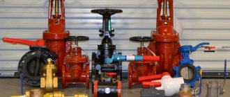
Valves are integral elements of any heating system (HC), regardless of the chosen circuit and configuration of the circuits. With the help of these simple devices, heat supply parameters are adjusted, ensuring the safety and stability of the system. This publication will discuss the main valves used in centralized and autonomous heating systems, their purpose, operating principle and design features.
[contents]
What is a balancing valve
For valves of this type, balancing is a change in the working cross-section of the pipeline. This is achieved by extending the rod into the working area of the structure through which the coolant flow passes. As a result, a change in pressure occurs, hydraulic normalization.
Outwardly, it resembles conventional shut-off and control valves. But for precise adjustments there is a digital scale on the lid. The design has fittings for connecting measuring instruments or a differential pressure regulator.
Features of work, purpose:
- The basic setting is carried out based on the hydraulic calculation of the system. In the future, it is possible to change the parameters for precise control.
- Installed in complex heating systems with several central risers.
- It is not used in collector heating, since balancing occurs automatically there.
- Not used in small autonomous heating systems, for houses with an area of less than 300 m².
There are differences for each model of balancing valve for a heating system - operating principle, design, ability to connect with other elements. The relevance of its installation is determined at the design stage. It is required for heat supply to apartment buildings, commercial and industrial buildings.
Important: the balancer is useless for an open heating system. It is installed only for closed lines with forced supply of coolant.
Piston water regulator: operating principle
In a piston regulator, the balance of incoming and outgoing pressure is achieved by a spring pushing the piston (see figure below). It works like this:
Water enters the first chamber, from which it passes into the second through an opening. When the pressure in the second chamber increases, it pushes the piston, which compresses the spring. The locking disc closes the passage hole and the pressure in the second chamber decreases.
When the water pressure decreases, the pressure in the first chamber decreases. The spring pushes out the piston and locking disc. Through the passage hole, water enters the second chamber and the pressure increases.
The device of a piston water pressure regulator.
The flow force can be adjusted by moving the spring and piston through the second chamber. For this purpose, such devices have an adjusting screw. By tightening it, you reduce the outlet pressure, and by unscrewing it, you increase it.
Why use it
The main task is hydraulic balancing. Example: in an apartment building there are two heating risers. In one the temperature is elevated, in the second it is below normal. The reason is that hot water follows the path of least resistance and most of the liquid goes into the circuit closest to the thermal unit. The distant pipeline accounts for less of the heat. By installing a balancing valve in critical areas, it is possible to normalize the temperature distribution for all consumers.
Alternative uses:
- A separate branch with radiators and a large distance between them. Optimizes hydraulic balance when the volume of flowing fluid changes due to the operation of thermostats.
- Into the circuit for the buffer tank. It regulates the supply of hot water to maintain a high temperature level. At the same time, the degree of heating in the main circuit does not decrease.
- In an indirect heating boiler. Artificial limitation of coolant flow to regulate temperature.
Balancing valves can be installed in one-pipe and two-pipe heating systems.
In the first case, they regulate the volume of hot water, in the second, they normalize the pressure between the supply and return pipelines. For the latter, models with one or two fittings are needed for connection to the differential pressure regulator. An alternative use is to measure pressure before and after the device using a combination pressure gauge. Three-way mixing valve for a heating system with a thermostat Modern technological processes must be automated. In a heating system, the main automation mechanism is the three-way valve. It is designed to mix two...Important: after a long period of inactivity, limescale may form on the stem. Before starting the heating test, you need to check the condition of the valve and clean it.
Three-way
There is practice to achieve a certain coolant temperature in various branches and CO circuits by mixing or separating coolant flows. The three-way valve on the heating system plays the role of a device that regulates the temperature of the working fluid after the heat generator.
The design of the mixing fittings is simple: there are three holes in the device body, two inlets and one outlet. Separating type devices have one input and two outputs.
The main control device of this element is a thermal head, inside of which there is a reservoir with liquid (bellows). When the remote sensor heats up, the liquid in it expands and enters the bellows. The volume of this reservoir increases and affects the valve stem, which opens or closes the inlets for mixing or separating flows. In separating types of this CO element, the same principle is used, but the rod does not open a passage for flows, but divides one flow into two.
It is not only the thermostatic head that can control the device. Manually controlled devices are quite popular. The depth of pressing of the rod is determined by the rotation of the control handle. Today, these devices with electric and servo drives are widely represented on the climate control equipment market.
Design Feature
To stabilize the pressure, you can choose a mechanical or automatic balancing valve for heating, which differ in design. The former are adjusted manually; to change the pressure difference, it is necessary to control the position of the rod each time.
If it is necessary to automate the operation of heat supply, it is recommended to choose models with a membrane unit.
Mechanical balancers
This is one of the types of shut-off valves, the position of the rod in which is adjusted manually.
The handle has a digital scale indicating the current flow rate in the pipeline. The advantage is that it can be used for balancing and as a shut-off valve. Example: shutting down individual sections of a pipeline for repair work. Additionally, you can install a pressure gauge and thermometer to monitor pressure and temperature. But for this you need to choose models with appropriate connectors. The material of manufacture is brass, less often stainless steel is used. When choosing, you need to pay attention to the maximum pressure that the device can withstand.
Automatic balancers
They consist of two components - a mechanical valve and a differential pressure regulator. In the first, a membrane block is installed; there are 2 fittings on the body, which are connected to a pressure gauge for adjustment or to a differential pressure regulator. When pressure changes, the thickness of the membrane block increases or decreases, thereby regulating the working passage of the line. Mounted on the return line.
The differential pressure regulator is installed on the supply pipeline. Connects to a mechanical balancer using capillary tubes. When heating parameters change, the pressure is automatically adjusted.
For large, branched systems, it is recommended to install automatic balancers. This is relevant for frequent pressure changes and changes in coolant temperature. If the system operates relatively stably, but you need to periodically monitor the hydraulic parameters, you can install mechanical balancers.
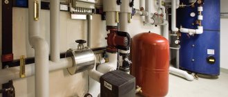
Automatic refill device
Due to various circumstances (natural evaporation, operation of a safety element, etc.), the volume of coolant in the CO may decrease. The less coolant, the more air in the system, which inevitably disrupts the circulation of water in the CO and overheats the boiler equipment. To prevent air from entering the system, it is necessary to replenish the amount of coolant in a timely manner. This can be done manually, or you can install a heating system make-up valve , thereby organizing automatic replenishment of CO coolant.
The design of this type of valve is practically no different from safety valves, but the principle of operation is exactly the opposite: as long as there is the necessary pressure in the CO, which props up the membrane to the seat, the spring is in a compressed state. When the pressure drops below the minimum, the spring straightens and moves the membrane away from the seat, allowing water from the reserve tank or water supply network to enter the CO. In Fig. The design of this device is shown below.
As the CO fills, the pressure in it increases, the spring compresses, and the membrane sits in the seat on the body, cutting off the replenishment.
Important! Selecting valves is a complex and important process that is best left to professionals.
Recommended Manufacturers
Several global manufacturers are engaged in the production of such shut-off and control valves. The operation of the heat supply depends on the quality of materials, accuracy of settings and design. Therefore, it is recommended to buy original models rather than analogues. This will increase the reliability of the system.
You can find balancers on the market from Valtec, Danfoss, Herz and Honeywell. They differ only in appearance, their functional features are the same. The table shows popular heating balancers from these manufacturers.
| Manufacturer | Mechanical balancer | Automatic balancer |
| Valtec | VT.042.G | VT.040.G |
| Danfoss | Leno MVT or MNT | AB-PM, APT or ASV |
| Herz | 4017 M | TS-V |
| Honeywell | Kombi-3-Plus | — |
These models differ in size and connection methods to the pipeline. Some of them are designed only for cold water supply, but most are universal and can be used for heating and water supply. An example is Danfoss products. Air valve for heating to bleed air from the battery In modern heating systems, a special device is provided to remove accumulated air - an air valve for heating. Without this device, the heating would not be able to work properly....
Mounting options
To ensure reliable and safe operation of the valve in the heating system, it is recommended that installation be carried out in accordance with all rules. You can find them in special regulatory documentation. The rules differ depending on the power and operating pressure of the system. But the basic principles still remain, including:
- In a heating system, this device must be installed on the supply pipe directly after the boiler. If the generator is large, it is possible to install two valves.
- The safety valve on the return pipe of heating systems is installed only to ensure hot water supply at the highest point of the boiler.
- It is also unacceptable to narrow the channel in places between the main line and the valve, and the installation of shut-off valves is unacceptable.
- Discharge pipes should be discharged into a sewer system or other safe place. The installation of shut-off devices on this line is completely unacceptable.
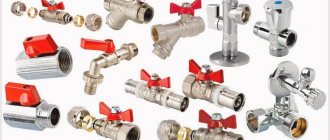
Shut-off valves
In heating systems, shut-off valves for heating are used to control the supply of coolant, as well as to open the circuit.
It allows you to control the heating process, making it more efficient and rational. In most cases, the shut-off valve on the heating radiator is installed in the radiator piping areas. In addition to functional advantages, this solution also has practical benefits - by closing the shut-off valve for the heating radiator, the homeowner will be able to repair the heating device without stopping the operation of the entire heating system. At the moment, shut-off valves for heating are represented by a wide range of devices. The following types of devices are often used in heating systems:
- shut-off valves;
- Ball Valves;
- needle valve;
- valves
These elements are made of durable metals that are resistant to corrosion and high temperatures. Shut-off valves protect the circuit from critical emergencies and increase the reliability of the heating system, helping to minimize the negative consequences of failure of an individual heating device.
Ball Valves
A ball valve is a shut-off valve for heating radiators, which is installed to regulate the flow of coolant. The design of the fittings includes a union nut, an internal thread, a plug and an air release device designed to bleed air from the system. When choosing this type of fittings, you need to pay attention to the material from which the valve is made and the presence of o-rings, which increase the service life of the element in the circuit. Brass taps have proven themselves well, as they are characterized by increased wear resistance and corrosion resistance.
Shut-off valves
This type of fittings is used to make it possible to replace radiators without draining the coolant from the circuit. Based on their design features, there are angle and straight shut-off valves. Moreover, some models can be equipped with a release mechanism to smoothly reduce the pressure in the circuit. Shut-off valves are characterized by a hose nozzle - it allows installation of the device as quickly and simply as possible.
Needle tap
The functions performed by a needle tap for heating can be different. Depending on the design, this device can perform locking, regulating and balancing functions. In heating systems, a shut-off needle valve for the heating radiator is most often used, which allows you to smoothly shut off the flow and avoid the occurrence of water hammer, which is detrimental to the system. Unlike a ball valve, which has two operating positions, a needle valve can operate in three positions:
- "closed";
- "open";
- "partially closed".
Valves
This type of valve performs exclusively a shut-off function. Due to its design features, it can operate in two modes - the mechanism is equipped with a locking element located perpendicular to the coolant flow. In the open position, the valve supplies coolant to the circuit, and in the closed position it prevents its circulation. Among the features of the valve, it is worth noting the low hydraulic resistance created in the circuit, the optimal diameter of the internal section, which coincides with the diameter of the pipeline, simple installation and high reliability.
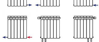
The concept of balancing
For a heating system to operate as efficiently as possible, it is important that it releases heat in such a way that it warms all rooms evenly. This will not only provide warmth and comfort in the house, but will also help reduce heating costs.
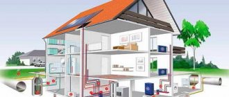
Heating systems can be divided into two types:
- Single-pipe or double-pipe. In them, the heated coolant moves through pipes from the heating boiler, giving off some of the heat to each radiator. Then the liquid that has lost heat enters the boiler again. After this, the cycle described here is repeated again.
- System with manifold connection. It has a distribution device, from which pipes go separately to each radiator. The adjustment occurs for each of them independently.
The last category includes heating systems that use not only radiators, but also heated floors.
The general principle of balancing is similar in different cases. Each radiator has an inlet valve. If they are all fully deployed, then the greatest heat loss in the first category of systems will occur in the first device. Further, increasingly cooled water will flow. To prevent this from happening, a valve is tightened in the initial batteries. Thus, the heat consumption will decrease and it will be enough for other heating devices.
Two-pipe system with heated floors Source eurosantehnik.ru
This procedure must be done in several steps to achieve the desired result. Between attempts, the batteries are given time to warm up properly.
For heating systems, regulation occurs by regulating the volume of incoming heated liquid. There should be so much of it that it is enough to heat each room.
The floors are adjusted in the same way, increasing or decreasing the heat supply. If the floors use heating based on the use of electrical energy, adjustment is made according to different rules, simply changing the settings.
Flow regulators, bypass valves, control valves, and pressure regulators are used to carry out adjustments. The layout of their installation depends on the specific type of heating system.
Thermostats occupy a special place. They have the most complete functionality. The device contains an electronic temperature sensor. The work takes place under the control of an electronic circuit. There is a simple and intuitive control panel.
The use of such electronic devices allows adjustments to be made at minimal cost. If necessary, it is possible to program the heating operation. For example, it is possible to reduce the heating temperature if the family is absent from the house for several days.
Water heated floors Source teplyiypol.ru
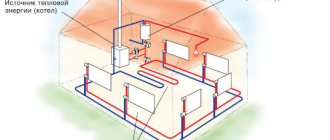
Heating control valves
It is designed to control the operation of the heating system as a whole or in a specific area. This depends on the design and operating parameters. Let's consider the most popular and mandatory models for installation.
Mayevsky crane
Design of the Mayevsky tap
If the heating of a certain radiator has significantly deteriorated, there is a high probability of an air lock. To prevent overheating of the coolant, it is necessary to pre-install Mayevsky taps on each of the heating devices.
This heating control valve is a needle valve that is completely sealed when closed. Installed on the upper radiator pipe, in case of air pockets it helps to eliminate them. To do this, use a key or screwdriver to loosen the degree of pressure on the curtain. This is done until the characteristic sound of escaping air is heard. The procedure ends only when the coolant begins to flow.
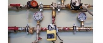
Distribution collectors and slurry collectors
The manifold distribution consists of large diameter pipes. Equalize the pressure in the pipeline. Such a collector is installed in a special distribution heating cabinet.
To remove sludge from the system, ball valves embedded in the manifolds are used. In addition to ball valves, the installations use magnetic dirt removers. The dirt removers have a special mesh arranged in the form of a fan. Thanks to this design of protection, various kinds of particles and small debris found in the water are retained, separated and discharged into a designated collection tank.
Distribution collectors and slurry collectors
Heating safety valves
In addition to the heating bypass valve, the normal operation of the system requires the installation of other types of control and safety valves. During heating operation, excess air may appear and the coolant will move back. To prevent these phenomena, it is necessary to provide in advance the installation of an air valve for heating and return.
Types of safety valves
Depending on the functional purpose, there are two types of safety valves - to remove air from the system and to prevent the reverse movement of water in the pipes. Without these elements, the operation of the system may be unstable, which will lead to a violation of the temperature regime, destabilization of pressure and the creation of emergency situations.
Installation of safety valves is carried out in the following areas of the system:
- In places with the highest probability of excess pressure - after boilers, circulation pumps, on collectors;
- A heating ball valve or its petal equivalent must be mounted on the return pipe. It is also necessary to install this component in the circulation pump piping;
- At the highest point of the circuit - to remove air from the system. A Mayevsky tap is installed on radiators and batteries.
Safety valves must not impair the performance of the heating system. First of all, they eliminate possible malfunctions in the heat supply. In the “inactive” state, these system components should not impair the speed of movement of the coolant or affect the temperature regime.
To prevent a sudden drop in pressure in the make-up unit, it is necessary to install a heating drain valve. It will prevent a sharp rise in pressure.
Heating air valve
During heating operation, air pockets may form in pipes and radiators. The reason for this is the high oxygen content in the water and the coolant temperature above +100°C. As a result, oxidation of metal components occurs and the temperature distribution changes. To avoid these situations, it is necessary to install valves to bleed air from the heating system.
Working principle of the air valve
First of all, the air valve for heat supply is mounted in the safety group along with the drain and pressure gauge. In the heating circuit they are located on a straight branch leading from the boiler. This place has the highest coolant temperature, as well as maximum pressure. In the manifold circuit, it is mandatory to install heat supply drain valves on each comb.
Criterias of choice
The number and parameters of valves required for a specific CO are selected at the calculation and design stage. The main criteria that influence the selection of these elements are:
- Type, circuit and configuration of CO.
- Temperature conditions (nominal and maximum).
- System pressure (working and maximum).
- Pipeline cross-section and thread type.
- Type of coolant (water, brines, antifreeze).
The operation of these devices stabilizes CO, making it effective and safe. Anyone who is independently installing a heating system in their home needs to know its purpose and operating principle. All valves can be divided according to their purpose into three categories: safety, control and regulation groups.
Everyone knows that any CO is an increased source of danger, since the coolant in the system is under pressure. And the higher the temperature, the higher the pressure (in closed CO). Next, let's look at the devices that are responsible for the safety of CO operation.
How to adjust the balancing valve in a heating system
Setting up a mechanical balancer
Before setting up the balance of the radiator network, you need to study the instructions for the valve, which are included when purchasing it. It indicates an adjustment scheme; if the user installs everything correctly, he can actually reduce the cost of thermal energy. The valve can be adjusted in two ways.
The first way to adjust the valve
This is the simplest and most proven adjustment option, which is recommended by experienced thermal regulators in water heating networks. To do this, you will need to divide the number of valve revolutions by the number of batteries installed in the heating circuit around the perimeter of the room. This technique makes it possible to correctly determine the step of the tuning algorithm. The method consists of closing all the valves in the reverse order - from the outermost to the first battery in relation to the heating source.
For example, for a dead-end circuit with 4 radiators equipped with mechanical balancing valves and a 4.5-turn spindle adjustment:
4.5:4 = 1.1 turns
Opening diagram:
- The first balancing valve is 1.1 turns.
- Second balancing valve – 2.2 turns.
- Third balancing valve – 3.3 turns.
- The fourth balancing valve is 4.5 turns.
The second way to configure the balancer
There is another, very high-quality method of balancing. It runs much faster, and contains the ability to take into account some of the specific location of the battery. The only thing you need to do this is a contact thermometer.
The complete process goes like this:
- Open all the valves and allow the network to enter temperature equilibrium with the operating temperature, for example, 80 C.
- Measure the temperature of all heating devices.
- Eliminate the difference by shutting off the first and middle taps. The end valves are not adjustable.
- Typically, the first valve turns no more than 1.5 revs, and the middle ones - 2.5 revs.
- Allow the system to reach temperature equilibrium for 20 minutes
- Temperatures are measured and valves are adjusted further if necessary.
Thermal valve
It is considered the most effective control valve for heating radiators. This device increases the practicality of the circuit and makes the heating process simple, good, and most importantly, healthy. The thermal valve can be mechanical or automated. Products of the first type consist of thermal and valve.
Automated models have a more complex design; they consist of these elements:
- temperature sensor - built-in or remote;
- programmer;
- automatic control systems.
An automated type mechanism is designed to regulate the temperature regime in the circuit in accordance with the settings that are pre-set by heat energy consumers. This device is sold at a high price, but it is fully justified, because with its help you can maximize the functioning of the heat supply system.
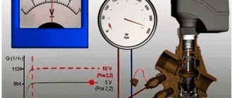
Overview of thermostats
Heating regulators include a valve and a thermocouple. The heat transfer is regulated using the valve. The operating principle is based on the distribution of water flow, which depends on the external temperature. The valve includes a spool, the height of which determines the flow capacity. Depending on the height, movements can be low-lift or full-lift.
Low-lift ones have a height of 0.05. For full lift - more than 0.25. The first type of thermostats is recommended for use where there is a small throughput (usually a liquid medium), the second type is most suitable for a gaseous medium.
In addition, valves can be spring and lever-load. In lever-loaders, the spool is combined with a lever. A load is hung on the lever. Thanks to the movement of the load, which is carried out along the entire length, the force of pressing the spool against the seat is adjusted.
When a difference occurs between the pressures of the medium and the lever, an automatic opening occurs and the flow of coolant into the discharge pipe is ensured.
In addition to the safety element, bypass and check valves are used, with the help of which the pressure in the heating system is also regulated. The principle of operation of these devices is similar to the principle of operation of the safety element. The only difference is that they are connected to the return line. They ensure the movement of water into the return pipeline when the pressure exceeds the permissible level.
The main parameters that must be taken into account when choosing these devices are the operating pressure. Their job is to pass water in one direction and exclude movement in the opposite direction.
Bypass valve
Calculation
The calculation of the safety device must be carried out in accordance with the methodology presented in SNiP II-35 “Boiler installations”.
Since manufacturers rarely indicate the actual height of the rod lift in the technical specifications, in the calculation this parameter is equal to 1/20 of the seat diameter. For this reason, the valve size as a result of this calculation is somewhat overestimated. In any case, after selecting a device, it is necessary to compare the thermal power of the heating system with the maximum power recommended in the technical description for the selected standard size.
Installation of a safety valve is required to protect the heating system from exceeding the pressure level above the maximum permissible value. For this reason, the calculation of this device should be reduced to calculating the maximum permissible increase in coolant volume and identifying possible sources of excess pressure.
Sources of volume growth can be:
- Overheating in a heat exchange or boiler unit with subsequent vaporization. When vaporizing, a liquid can increase its volume by 461 times, so this factor is the predominant factor when choosing a valve.
- Failure of automatic control of make-up lines of boiler houses and independent heating systems. This may also be a predominant factor in valve selection.
- The coolant, heating up in a heat exchange or boiler unit, increases in volume. When heated, the specific volume increase is from 0 to 100 °C, which is only 4%, so when selecting the size of a device of this type, this is not a fundamental point.
The selected equipment must ensure the discharge of the calculated amount of coolant, according to the most significant factor in the increase in volume.