A person physically cannot stay in the boiler room all the time to monitor the health of the heating line, temperature readings and pressure level of the heating device. The main assistants in this matter are additional devices that automatically monitor the functioning of the system.
We will tell you what devices the heating safety group includes, how they operate, and how they protect the system. Taking into account our advice, you can easily select the necessary components. The article describes the rules for assembling and connecting this important link, which is responsible for trouble-free operation.
Security block design
The main reasons for a malfunction in a closed boiler system are increased pressure or excessive filling of the pipeline with coolant, i.e. water. The boiler heat exchanger is the first device to react to such deviations, which is why it fails.
Why might an accident happen?
To prevent such failures in the heating system, a safety unit is used. With its help, the required coolant pressure is achieved in the boiler, pipeline and batteries.
At the moment of excessive pressure, the excess heated coolant is discharged. Emerging emergency situations, such as overheating of a water heating boiler, lead to an increase in pressure in the line. This process is a consequence of exceeding the temperature norm of the coolant.
When heated, the liquid tends to expand, which a closed-type heating system is not designed for - an expansion tank is included in its circuit as an additional reserve. However, its volume is also limited.
Any heating system is under pressure. For low-rise buildings, correctly installed devices that provide coolant create a pressure of 1-2 bar during heating and cooling cycles
The consequence of increased pressure is failure of boiler elements or rupture of the line. To control the pressure and, in the event of a potentially dangerous situation, adjust it to the optimal value, you will need a mounted safety group.
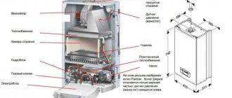
Structurally, the device is formed from the following modules: automatic air vent, pressure gauge and safety valve. All these devices are mounted in a galvanized steel housing with threaded connectors, with or without thermal insulation.
Automatic air vent
In most cases, the automatic air valve for a security system is made of brass.
Air bubbles in the heating system appear due to the following factors:
- initial filling of the heating line with liquid;
- installation of poor-quality or worn rubber seals;
- blockage with corrosive deposits inside the pipeline;
- water replenishment;
- incorrect installation or commissioning of the heating system, etc.
The water entering the heating circuit contains a lot of oxygen, which, when heated, begins to expand, forming air pockets. Due to their formation, the pressure increases and the coolant circulation rate slows down.
The automatic type of air vent has a special design of the air chamber: dirt particles cannot get inside, and due to the large volume of the air chamber, the problem of blocking the air duct is eliminated
To prevent this from happening, it is advisable to install an automatic air release device, which is easy to use - it does not require adjustment with human intervention.
The principle of operation of the device depends entirely on the design features. The automatic device consists of a channel and a valve. The second element is responsible for removing excess air. If there is no excess pressure in the pipeline, the float is in the raised position, and the needle valve is in the “closed” position.
At the moment an air lock forms, the float will lower and the rocker arm will open the valve - this is how air is released from the system. After removing the excess, the float will return to its original position and the valve will be closed again.
Pressure gauge - an accurate indicator of pressure
The operation of the pressure gauge is designed to measure pressure in the heating system. This device was created to quickly obtain, check and adjust the acceptable level of indicators. Its main characteristic is the determination of accurate data.
In second place is the quality of reliability. For some, the size of the dial is also important for ease of viewing readings. Each pointer mechanism has its own measurement inaccuracy. This error is scattered as follows: at the edges of the scale it has a maximum value, in the center it has a minimum.
The pressure gauge has two arrows: red and black. The first indicates real data, the second is set to a point that is critical for the system
For each heating mechanism, the accompanying documentation specifies the maximum permissible pressure level that it can withstand. Bars or atmospheres are used as measuring units in pressure gauges. However, the first measurement option has become widespread.
Bars have an intermediate meaning and are as close as possible to the physical and technical atmospheres:
- 1 bar = 10.197 m of water column or 0.1 MPa
- Technical atmosphere (1 atm) = 10 m water column
- Physical atmosphere (1 atm) = 10.33 m water column
An indicator of 1.5 atmospheres is the standard pressure value in pipelines of independent heating systems. Therefore, for an autonomous boiler room, a pressure gauge with a maximum (end of the scale) of 4 atmospheres will be sufficient.
The maximum pressure for which the pressure gauges are designed is 10 atmospheres. Also on the market are devices for 8, 6 and 4 atmospheres
Features of Safety Valve
In a heating system, the safety valve plays an important role. This is a protective device designed for heat generators. The main function is to eliminate loads (drops) when unplanned situations arise. This problem is most pressing for steam-type heating systems.
However, high blood pressure can also occur due to the following problems:
- Due to a malfunction of the automation, the volume of coolant may exceed the permissible limit.
- Rapid increase in temperature in the circuit.
This device also tends to regulate the flow of coolant in the heating line. This is a stamped structure consisting of a brass body equipped with two parts - a membrane and a steel spring. As a rule, at the moment the fuse trips, about 100 g of heated liquid must be eliminated to normalize heating operation.
The brass safety valve can withstand coolant temperatures up to 120 °C. The rod and coil spring in this device are made of stainless steel
Due to the flexibility of the first element, the required pressure coefficient acting on the membrane is established. Consequently, the membrane partition blocks the passage to the outside. By changing the degree of compression of the spring in the safety valve, the functions of the safety mechanism in the heating system are regulated.
It is necessary to adjust the protective mechanism in such a way that the maximum possible pressure is 15% greater than the working pressure. The valve adjustment process is carried out every year on the eve of the heating season.
The functionality of the device is checked by forcing it to open. This should be done at certain intervals so that the reset mechanism does not become clogged with various deposits while in a non-working position.
When checking the functionality of the safety valve, the forced release of the coolant is performed using a special handle. An arrow on the device body indicates the direction of hot air exit.
The following article will introduce you to the features of the operation and installation of a safety valve for a boiler, in which the device is disassembled in detail and installation diagrams are provided.
How to connect a solid fuel boiler
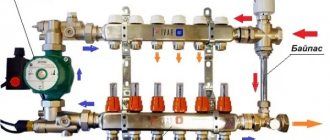
The canonical connection diagram for a solid fuel boiler contains two main elements that allow it to function reliably in the heating system of a private home. This is a safety group and a mixing unit based on a three-way valve with a thermal head and a temperature sensor, shown in the figure:
The always open output of the mixing valve (the left pipe in the diagram) must be directed to the pump and heat generator, otherwise there will be no circulation in the small boiler circuit
The presented diagram shows how to connect the unit correctly and is used with any solid fuel boilers, including pellet ones. You can find various general heating schemes - with a heat accumulator, an indirect heating boiler or a hydraulic arrow, in which this unit is not shown, but it must be there. The method of protecting against moisture loss in the firebox is discussed in detail in the video:
The task of the safety group, installed directly at the outlet of the supply pipe of a solid fuel boiler, is to automatically relieve pressure in the network when it rises above a set value (usually 3 Bar). This is done by a safety valve, and in addition to it, the element is equipped with an automatic air vent and a pressure gauge. The first releases the air appearing in the coolant, the second serves to control the pressure.
How the scheme works
The mixing unit, which protects the heat generator from condensation and temperature changes, operates according to the following algorithm, starting from kindling:
- The firewood is just starting to burn, the pump is on, the valve on the side of the heating system is closed. The coolant circulates in a small circle through the bypass.
- When the temperature in the return pipeline rises to 50-55 °C, where the attached remote-type sensor is located, the thermal head, at its command, begins to press the three-way valve stem.
- The valve slowly opens and cold water gradually enters the boiler, mixing with hot water from the bypass.
- As all the radiators warm up, the overall temperature increases and then the valve closes the bypass completely, passing all the coolant through the heat exchanger of the unit.
This piping scheme is the simplest and most reliable; you can easily install it yourself and thus ensure the safe operation of the solid fuel boiler. There are a couple of recommendations regarding this, especially when piping a wood-burning heater in a private house with polypropylene or other polymer pipes:
- Make the section of the pipe from the boiler to the safety group from metal, and then lay plastic.
- Thick-walled polypropylene conducts heat poorly, which is why the surface-mounted sensor will openly lie, and the three-way valve will lag. For correct operation of the unit, the area between the pump and the heat generator, where the copper flask is located, must also be metal.
Connecting with copper pipes will not protect polypropylene from destruction in the event of overheating of the TT boiler. But it will allow the temperature sensor and safety valve on the safety group to work correctly
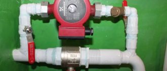
Another point is the installation location of the circulation pump. It is best for him to stand where he is shown in the diagram - on the return line in front of the wood-burning boiler. In general, you can install the pump on the supply side, but remember what was said above: in an emergency, steam may appear in the supply pipe.
The pump is unable to pump gases, so when the chamber is filled with steam, the impeller will stop and the coolant circulation will stop. This will speed up a possible explosion of the boiler, because it will not be cooled by water flowing from the return.
Way to reduce the cost of strapping
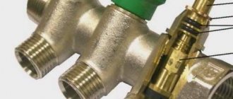
The condensate protection circuit can be reduced in cost by installing a three-way mixing valve of a simplified design that does not require connecting an overhead temperature sensor and thermal head. It already has a thermostatic element installed, set to a fixed mixture temperature of 55 or 60 °C, as shown in the figure:
Special 3-way valve for solid fuel heating units HERZ-Teplomix
Installing such an element definitely allows you to save on piping the TT boiler. But in this case, the possibility of changing the temperature of the coolant using a thermal head is lost, and its deviation at the output can reach 1-2 °C. In most cases, these shortcomings are insignificant.
Operating principle of the safety unit
The security group works according to an extremely simple scheme, where each of the modules is responsible for maintaining the standards of certain indicators in a private boiler room:
- Thanks to a convenient pressure gauge, the user can monitor the pressure readings at the moment the line is filled with coolant, as well as during the operation of the boiler.
- The safety valve protects the heat generator from critical pressure drops.
- The main functionality of the air vent is based on the automatic release of air entering the pipeline during its initial filling or during operation.
All safety modules are represented by a single unit and are equipped with a special housing - a manifold.
Provided that the boiler room circuit uses an open type expansion tank, installing a safety group does not make sense - the pressure in the pipeline is equal to atmospheric pressure, and excess air leaves the system through the tank capacity.
Regardless of the type of boiler used (solid fuel, gas, diesel), the protective unit is considered the main emergency element of a closed heating system, which tends to work with excess pressure
Closed heating system: what is it, how it works, pros and cons
In such schemes, expansion membrane tanks are used. The sealed container is divided into two parts by an elastic membrane.
As the temperature increases, the valve opens and excess liquid moves into the tank.
When the temperature drops, the coolant flows back into the system, due to which a stable pressure is maintained in the latter.
A non-pressure tank can be completely filled with liquid, so the pressure maintenance installation must be more compact than that of a conventional tank. It allows you to adjust the specified parameters in the circuit and automatically recharge the structure.
A closed circuit consists of the following elements:
- from a sealed membrane tank;
- from batteries (radiators);
- from a heating boiler;
- from the circulation pump;
- from pipes;
- from connecting elements (valves, taps, filters).
A closed heating circuit has a number of advantages:
- possibility of using any coolant;
- durability of the structure due to complete tightness;
- absence of unnecessary noise;
- possibility of self-installation of the system;
- high speed of fluid movement, ensuring maximum heat transfer;
- no need for thermal insulation for the main line;
- reduction of financial costs for heating the house.
Disadvantages include dependence on electrical energy and the need to purchase a large membrane tank, the price of which is quite high. The problem of energy dependence is solved by installing uninterruptible power supplies or small generators that provide emergency power supply.
Design diagrams, use in apartment buildings
In private houses, a single-pipe or two-pipe heating circuit is used.
The single-pipe scheme is used in rooms with a small area, where no more than five radiators are required for heating.
Photo 1. Diagram of a closed heating system with a single-pipe circuit. Each of the radiators is connected in series.
All batteries are connected in series in the circuit, so the last heating device will always be colder than the first. The obvious advantage of this scheme is lower pipe consumption.
If one battery fails, the others will continue to operate normally when using the bypass. The single-pipe system can be horizontal or vertical. The horizontal one does not allow you to regulate the amount of coolant, so bypasses are installed when laying it. A vertical single-pipe circuit is in most cases used in high-rise buildings.
The two-pipe (double-circuit) circuit heats the rooms more evenly. The liquid from the heat generator to the batteries circulates through two circuits. In this case, radiators are connected in parallel. The coolant has the same temperature in all batteries. This method is much more expensive, but it makes it possible to regulate the temperature in each room.
Calculation
In order to correctly select the circulation pump and pipe diameters, a hydraulic calculation of the heating circuit is carried out. It allows you to identify hydraulic pressure losses in specific areas and minimize operating costs.
Attention! It is advisable to install the circulation pump in the return pipeline. In this case, the service life of the device will increase, since already cooled coolant will pass through it. Calculations are carried out by a specialized specialist using thermal engineering calculations and after selecting batteries
As a result of the calculations, the pressure value required to circulate water through the circulation pump will be obtained. After this stage, the value is calculated to determine the volume and selection of the membrane tank
Calculations are carried out by a specialized specialist using thermal engineering calculations and after selecting batteries. As a result of the calculations, the pressure value required to circulate water through the circulation pump will be obtained. After this stage, the value is calculated to determine the volume and selection of the membrane tank.
Equipment selection rules
For each model of the protective block, the accompanying documentation specifies the parameters for which it is designed.
The main criteria influencing the choice of device:
- thermal characteristics of the boiler for which the unit is designed, kW;
- maximum coolant temperature, °C;
- nominal pressure;
- compatibility with coolant - water, steam or antifreeze;
- diameter of the connecting thread - if there is a mismatch, it will be enough to purchase adapters of the required diameter.
Correct selection of the power of the safety unit ensures reliable protection of the boiler from any malfunctions in the operation of the heating circuit.
Trigger algorithm
Let us briefly summarize the principle of operation of the entire group. From the very beginning of commissioning, an automatic air vent operates, removing all air from the system. However, if it overheats and reaches critical pressure levels, it is powerless. To avoid an emergency, the safety valve is activated, releasing excess coolant, thereby reducing the pressure in the system.
To monitor the operation of the system, the safety group includes a pressure gauge that shows the pressure at the moment: low pressure indicates depressurization, a malfunction of the expansion tank or make-up valve; increased - about expansion of the coolant or excessive release of steam due to overheating.
Rating of popular models
Among the manufacturing companies involved in the development of safety valves, the following popular companies can be distinguished: Watts and Valtec. The manufacturer Watts is famous for its fairly extensive range of devices for the heating system, among which the safety unit occupies an important place.
The KSG series has various threaded body devices, differing in their sizes (from standard to compact) and material of manufacture:
- cast iron;
- steel;
- brass.
Additionally, some models come complete with heat-insulating casings. Units from the KSG line are typically equipped with a relief valve designed for a critical pressure of 3 bar. Installation into the heating main is carried out using a 1-inch diameter connector with internal thread.
The KSG model range from Watts, designed for operation in a boiler room with heat generators with a capacity of 50-200 kW
Valtec is not inferior in quality to its products to the previous brand. The company presents a line of devices for boilers and expansion tanks - the VT 460 and VT 495 series, respectively.
The VT 460 model range is designed to operate with domestic heating units with a power of up to 44 kW, at a maximum pressure of 3 bar. However, the prices for ready-made devices are far from cheap, so the solution of self-assembly of such a unit can be called advisable.
Valtec develops protective blocks designed for all types of heat generators. A characteristic feature of the VT 460 series is the packaging of safety group modules in a compact brass housing
Manufacturers
The greatest demand is for security groups from Valtec and Watts. Their products are distinguished by high quality workmanship and reliability. For example, VT.460.0.0 from Valtec is used for heating systems with a nominal pressure of up to 10 bar. The maximum temperature of use should not exceed +120°C. Steam, water or a special liquid can be used as a coolant.
The emergency valve has a fixed setting of 3 bar. The body of the safety group is brass, nickel plated. The thread for connection is internal, size 1″. The cost of the VT.460.0.0 group starts from 1,700 rubles.
Security Groups from Watts
The WattsKSG-MS security group has similar characteristics. The body is made of brass, but unlike the previous device, it is located in a heat-insulating casing. The emergency valve response threshold is 3 bar.
When installing the safety group and other parts of the heating system, you must strictly follow the instructions supplied with them from the manufacturer. Because if installed incorrectly, the system will not work properly, or an error made during installation will lead to its breakdown.
Assembling the security unit yourself
There shouldn't be any difficulties in making the safety unit.
To start the process, you will need to prepare the following modules and tools:
- relief valve;
- pressure gauge;
- air vent;
- wrench;
- gas keys;
- two squares with a threaded connection of external and internal type;
- union;
- crosspiece;
- adapters;
- sealant;
- sanitary flax for sealing and sealing joints.
Initially, the squares must be screwed into the crosspiece. For a tight connection, the flax strands are wound onto the threads in a clockwise direction, and the distribution of the sealant over the surface should be the same.
The cost of a self-made safety unit for a heating system is approximately two times less than analogues offered on the market
A thin layer of sealant is applied on top of the threads. Next, using a wrench, screw the squares into the crosspiece perpendicular to one another.
Now you need to install the pressure gauge, safety valve and air vent. If parts have different diameters, appropriate adapters are used. After the final assembly of all modules, the operation of the mechanism must be checked under pressure - the device should not leak, and all parts should be in working condition.
Choice
It is important to select a safety group that exactly matches the characteristics of the assembled heating system. Each element of the group, pressure gauge, safety valve and air vent has its own technical and operational characteristics, which must exactly meet the requirements of the heating project
Manufacturers offer ready-made solutions and safety group assemblies based on the most common home heating options, for various boilers and wiring methods.
Before you make your choice, you should carefully read the technical manual for your boiler. If it is a wall-mounted gas or electric boiler, then it already has a safety group, which is fully consistent with its parameters, so there is no need to duplicate it. In the case of floor-standing boilers, solid fuels, stoves and fireplaces with a water circuit, in most cases there is no built-in equipment or piping. Read about how to choose a heating boiler here.
All elements of a security group are pinned to a single console. This is actually a pipe with prepared triplets for connecting equipment and two outlets for inclusion in the heating circuit.
When choosing, you should clarify:
- Diameter for connection pipes (1', ¾', ½').
- Connection option (corner, bottom, side, etc.), from which side the pipes should be brought to the safety group, and how exactly to orient it.
In any case, the air vent is mounted at the top point of the group. So it should remain connected. Below it there is a pressure gauge and a safety valve. This is done to ensure that air accumulating in the air chamber does not affect the pressure gauge readings and the operation of the explosion valve.
Material for the manufacture of the safety console: nickel, stainless steel, bronze, cast iron.
Cast iron is used only for high-pressure and efficient heating systems with a large cross-section of pipes in the distribution. These are mainly collective industrial boiler houses. For a private home, it is better to choose nickel or stainless steel. In this case, the console and equipment can simply be covered with an outer casing made of black cast iron for additional protection.
Pressure gauge
Two main characteristics:
- permissible measurement range (upper and lower limit);
- accuracy of measurement and indication of readings (scale and error).
The measurement range must cover, with a margin of 0.5-1 bar, the nominal pressure in the system and permissible deviations during operation.
Let’s say that the nominal pressure for heating is 3 atm. The permissible deviation downward will be equal to 1.5 atmospheres. A decrease below 1.5 atm will be considered a signal for an emergency. The upper limit will be 4.5-5 atm, after which the safety valve should inevitably operate. Accordingly, the pressure gauge range should be from 1 to 5-6 atm. It is desirable that the scale be as accurate as possible and indicate areas of attention. In this case, the scale is divided conditionally into 3-4 zones, marked with color markers, so that even with a quick glance you can react to any deviations.
Air vent
Characterized by the operating pressure in the system and response parameters. Almost all automatic valves are adjustable to set the optimal pressure and response conditions. If you set the adjustment knob to the minimum position, then at the slightest accumulation of air the valve will operate. At the maximum setting, the valve operates less frequently, but at the same time accumulates more air. It is difficult to say which installation would be more appropriate. It is easier to leave the factory settings unchanged if the heating system is installed independently.
Safety valve
The main parameter of the valve is the response pressure. The upper pressure limit in the circuit, upon reaching which the valve opens and releases part of the coolant. It is based on this characteristic that you should choose a security group first. The response pressure can be adjusted only within small limits.
It is useful to clarify in advance how to install the safety group and determine how and in which direction the valve discharges water. The discharge fitting should be oriented away from the main equipment and the heating boiler. It is necessary to select a hose for draining into the sewer.
Connection to the heating system
First of all, it is necessary to correctly determine the installation location of the security group.
There are certain requirements that must be met:
- this should be a horizontal section of the pipeline next to the heat generator;
- on the supply line after the boiler;
- some boilers provide for installation of a safety unit directly on the unit itself; for this purpose there is a special connector on top of the heat generator;
- the distance from the heating device to the protective block should not exceed 1.5 meters, less is possible;
- for a pipe running vertically upward from the boiler, for example, to the next floor, it is necessary to arrange a branch. This is done using a corner so that the safety group can be positioned in a horizontal plane and the units look “heads up”;
- for a very powerful boiler, it may be necessary to install another protective unit.
A very important rule that must be followed is that shut-off valves are not installed between the safety group and the boiler. It would be advisable to install a protective block up to the first shut-off valve located on the line.
To avoid injury when checking or when the safety valve is activated in the presence of a person, it is necessary to connect a drainage tube to the device and drain it into the sewer
It is worth checking the functionality of the safety valve in a timely manner. This procedure is performed using the following method - after installation, open the cap in the direction indicated by the arrow on the device.
After installing the protective device, it is necessary to check the correct operation of all modules. To start using the air vent, you will need to unscrew the top cap and bleed the air. Now the lid is returned to its original position, but the device must remain slightly open.
How to tie solid fuel boilers
The connection diagram for a wood-burning heat generator is designed to solve 3 problems (in addition to supplying the batteries with coolant):
- Preventing overheating and boiling of the TT boiler.
- Protection against cold “return” and excessive release of condensate inside the firebox.
- Work with maximum efficiency, that is, in full combustion mode and high heat transfer.
The presented wiring diagram for a solid fuel boiler with a three-way mixing valve allows you to protect yourself from condensation in the firebox and bring the heat generator to maximum efficiency mode. How it works:
- While the system and heater are not warmed up, the pump drives water through the small boiler circuit, since the three-way valve is closed on the radiator side.
- When the coolant heats up to 55-60 degrees, the valve set to the specified temperature begins to mix in water from the cold “return”. The heating system of a country house is gradually warming up.
- When the maximum temperature is reached, the valve completely closes the bypass, all water from the TT boiler goes into the system.
- A pump installed on the return line pumps water through the jacket of the unit, preventing the latter from overheating and boiling. If you put the pump on supply, the chamber with the impeller can fill with steam, pumping will stop and the boiler is guaranteed to boil.
The principle of heating using a three-way valve is used for piping any solid fuel heat generators - pyrolysis, pellet, direct and long-term combustion. The exception is gravity distribution, where the water moves too slowly and does not provoke condensation. The valve will create high hydraulic resistance, preventing gravity flow.
If the manufacturer has equipped the solid fuel unit with a water circuit, the coil can be used for emergency cooling in case of overheating. Please note: the fuse on the safety group is triggered by pressure, not temperature, and therefore is not always able to protect the boiler.
A proven solution is to connect the DHW coil to the water supply through a special thermal relief valve, as shown in the diagram. The element will be triggered by a temperature sensor and at the right moment will pass a large volume of cold water through the heat exchanger.
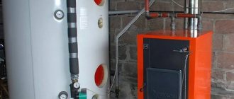
Using the Buffer Capacity
The best way to increase the efficiency of a TT boiler is to connect it to heating through a buffer tank. At the inlet of the heat accumulator we assemble a proven circuit with a three-way mixer, at the outlet we install a second valve that maintains the required temperature in the batteries. Circulation in the heating network is ensured by a second pump.
A balancing valve on the return line is needed to adjust the performance of the pumps
What we gain thanks to the thermal accumulator:
- the boiler burns at maximum and reaches the declared efficiency, fuel is used efficiently;
- the likelihood of overheating is sharply reduced since the unit dumps excess heat into a buffer tank;
- the heat accumulator plays the role of a hydraulic arrow; several heating branches can be connected to the tank, for example, radiators of the 1st and 2nd floors, floor heating circuits;
- a fully heated tank maintains the operation of the system for a long time when the wood in the boiler firebox has burned out.
TT boiler and storage water heater
In order to load an “indirect” boiler using a wood heat generator, you need to embed the latter into the boiler circuit, as shown in the picture. Let us explain the functions of individual elements of the circuit:
- check valves prevent the coolant from flowing in the other direction along the circuits;
- the second pump (it is enough to take a low-power model 25/40) provides circulation through the spiral heat exchanger of the water heater;
- the thermostat turns off this pump when the boiler reaches the set temperature;
- An additional air vent prevents the supply line from becoming aired, which will be above the standard safety group.
In a similar way, you can connect the boiler to any boiler that is not equipped with an electronic control unit.
Date: September 25, 2022
Summarizing
You can regulate heating radiators using several types of devices, but experts believe that the best solution is to use special control valves. Such products are manual taps and automated products - thermostats, and only in some cases can a three-way valve with a thermal head be used.
In high-rise apartments with centralized heating, it is better to give preference to control taps or a three-way valve. As for individual heating systems, the problem of how to reduce the temperature of the coolant in a heating radiator is solved using thermostats.
If the apartment owner still prefers automatic adjustment of radiators, then a filter should be installed before the thermostat - it will trap most of the various impurities.