A huge number of electrical appliances used in everyday life and industry base their operation on determining the level of ambient temperature. The measuring element in them is a temperature sensor that is triggered when heated or cooled to a set level. They can be purchased in most stores; they are included with ovens, controllers and other devices, but it is much more interesting to make a thermostat with your own hands.
Example of a simple thermostat
Next, we will look at the principle of operation and options for making such a homemade product.
How it works?
Before you make a thermostat with your own hands, you need to understand the accompanying theory. The principle of this device is identical to the operation of simple measurement sensors that can change resistance depending on the surrounding temperature conditions. A special element is responsible for changing the indicator, and the so-called reference resistance remains unchanged.
In the thermostat device, an integrated amplifier (comparator) reacts to changes in the resistance value, switching the microcircuits when a certain temperature is reached.
Required materials and tools
In some situations, you will need the skills to make a complex printed circuit board. The simplest circuits are assembled in a few minutes using a soldering iron and surface-mounting technology. Before performing work operations, you must purchase:
- components;
- Consumables;
- measuring equipment.
The shopping list is compiled based on the selected electrical circuit. To protect the device from adverse external influences and improve its appearance, an appropriate housing is created.
What should the scheme be?
On the Internet and in regulatory documentation, it is easy to find diagrams of thermostats for various purposes that you can assemble with your own hands. In most cases, the basis of a schematic drawing is the following elements:
- Control zener diode, designated TL431;
- Integrated amplifier (K140UD7);
- Resistors (R4, R5, R6);
- Quenching capacitor (C1);
- Transistor (KT814);
- Diode bridge (D1).
The circuit is powered by a transformerless power supply, and a car relay designed for a voltage of 12 Volts is ideal as an actuator, provided that the current supplied to the coil is at least 100 mA.
Creating a simple thermostat
When repairing household electrical appliances, you may have encountered a situation where the thermostat failed. Although this is a small microcircuit installed to control the amount of heating or cooling of something.
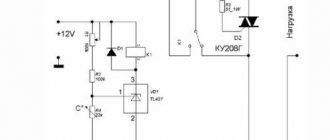
Alas, the cost of such a factory-made element is quite high, so it is much more profitable to assemble the thermostat yourself. A diagram of a fairly simple homemade thermostat is shown in the figure below.
Rice. 5. Diagram of a simple thermostat
To make it you will need:
- step-down transformer from 220 to 12 V;
- six diodes (in this example, IN4007 are used);
- capacitors 47 µF, 1 mF and 2 mF;
- microcircuit for a 5V stabilizer;
- transistor (in the example under consideration it is KT814A);
- Variable zener diode (TL431);
- resistive elements at 4.7; 160, 150 and 910 kOhm;
- resistor with variable resistance 150 kOhm;
- temperature dependent resistor 50 kOhm;
- Light-emitting diode;
- electromagnetic relay 100 mA with a supply voltage of 12V (in the example under consideration, an automobile version is used);
- button and body.
The manufacturing process consists of the following stages:
- Using a soldering iron, assemble the above parts onto a printed circuit board as shown in the diagram above.
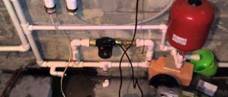
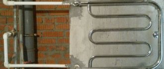
- After this, take the measuring element for the thermostat out into the open space to install it in the desired location.
Rice. 6. Output the measuring element
- Install a variable resistor on a rigid frame and apply a temperature scale to set up the device.
Rice. 7. Install the regulator on the frame and apply the graduation
- Connect the power cord to the terminal block.
Connect the power cord to the terminal block.
In this case, the terminal block was taken from an old device located in the housing.
- Connect all separately placed elements to the board and cover with the housing.
After assembling the thermostat, it can be installed in any place, for example, for heating and connected to the power circuit of an electric boiler. If the heating radiators heat the room to the set temperature, the relay contacts will break the circuit and stop the power supply. When the digital thermometer cools down, the heating will turn on again and heat up again. If you are not satisfied with the temperature regime, you can change it by setting the sensor.
How to do it?
Instructions for making a thermostat with your own hands are based on strict adherence to the chosen scheme, according to which it is necessary to connect all the components into a single whole. For example, an electronic circuit for an incubator is assembled using the following algorithm:
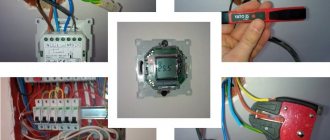
- Study the image (it’s better to print it out and put it in front of you).
- Find the necessary parts, including the case and board (old ones from the meter will do).
- Start with the “heart” - the K140UD7/8 integrated amplifier, connecting it with a positively charged reverse action, which will give it the functions of a comparator.
- Connect the negative resistor MMT-4 in place of “R5”.
- Connect the remote sensor using shielded wiring, and the cord length can be no more than a meter.
- To control the load, include thyristor VS1 in the circuit, installing it on a small radiator to ensure adequate heat transfer.
- Set up the remaining elements of the circuit.
- Connect to the power supply.
- Check functionality.
By the way, by adding a temperature sensor, the assembled device can be safely used not only for incubators, drying, but also for maintaining the thermal regime in an aquarium or terrarium.
Concept of temperature controllers
Products in this category are used to solve various problems. Based on the appropriate temperature threshold setting, power is supplied (turned off):
- heating in the cellar;
- heating the soldering station;
- boiler circulation pump.
From the examples given, the basic requirements for accuracy that a suitable thermostat circuit must provide are clear. In some situations it is necessary to maintain a given level no lower than ±1C°. To monitor operating parameters, an operational indication is needed. Load capacity is essential.
The listed features explain the purpose of typical functional units:
- the temperature value is recorded with a specialized sensor (resistor, thermocouple);
- the readings are analyzed by a microcontroller or other device;
- the actuator signal is sent to an electronic (mechanical) switch.
For your information. In addition to the parts discussed, the thermal relay circuit may contain additional components to supply power to an electric heater or other powerful load.
How to install correctly?
In addition to high-quality assembly, it is necessary to pay attention to the operating conditions, which should include:
- Placement: lower part of the room;
- Dry room;
- The absence of nearby “knocking” units: emitting heat or cold (electrical equipment, air conditioning, open door with a draft).
Having figured out how to connect a thermostat with your own hands, you can start using it regularly. The main thing is that the power of the manufactured device is designed for the relay contacts. For example, with a maximum load of 30 Amps, the power should not exceed 6.6 kW.
Examination
Test the thermostat in this order:
- bring a burning match or lighter to the thermistor and the cooler should start working;
- when cooling, the fan should turn off;
- if the circuit does not work, you need to recheck the soldering and contacts.
TR - thermistor, K - cooler, R1 - variable resistor, PT - field-effect transistor, AB - 12 V battery.
Using a thermal sensor on Arduino
To assemble a temperature meter based on an Arduino microcontroller, you need to prepare the following:
- Arduino UNO;
- connectors;
- circuit board;
- digital module DS18B20 (range from −56 to +1250 C).
The DS18B20 digital temperature sensor is a device that not only signals when a specified temperature threshold has been exceeded, but can also store measurement values. The sensor chip has three output contacts - “+”, “−” and a signal wire. The waterproof temperature sensor is used to measure the heating of water or liquids.
A temperature sensor can always be purchased, like an Arduino board, in online stores. The digital module is connected to Arduino via GND channels, and the Vdd output is connected to 5V, Data to any Pin. For a clearer understanding, the connection diagram of the DS18B20 digital sensor to Arduino is shown in the photo below.
DIY temperature sensor
Author: Sir Murr Published 01/01/1970
Temperature measurement is one of the most vital types of measurements both in everyday life and at work. An electronic thermometer is a useful thing, especially if it is digital. The characteristics of a thermometer are primarily determined by the primary temperature sensor
, or a thermal converter.
For brevity, we will simply call it sensor
. The most popular types of sensors are shown in the table.
There are also more exotic temperature sensors - manometric, quartz non-temperature compensated resonators, pyrometric sensors, and others that even the Wise Cat does not know about. Thermocouples are most often used due to their low cost. This is good for industry when the thermocouple performance is known. The most commonly used types are XA (K) with a maximum operating temperature of +1300 o C, and XK (L) with a maximum temperature of +850 o C. Other types of thermocouples are more scarce. You can make a simple thermocouple yourself, for example, for a soldering station - take one wire from the filament holder of a light bulb, and the other wire - iron or copper, twist their ends with pliers - and voila - the thermocouple is ready! But the reliability of such a solution is very doubtful; it is still better to weld the ends of the thermocouple in a gas burner. You will also have to take the temperature characteristics of this thermocouple yourself. We published on our website practical implementations of thermometers based on a semiconductor sensor and a thermocouple. Methods for calibrating thermometers on these sensors were also discussed there. Now we will look at the design of an RTD thermometer. As already mentioned, sensors of this type have the highest linearity (or, more precisely, monotonicity) and repeatability of characteristics.
By the way, it is worth noting that all reference books reprint the same information about the unusually high linearity of such sensors. But it is enough to construct a graph of the characteristic, and its nonlinearity will be visible. The proportionality coefficient between the temperature change and the signal increment is called the Seebeck coefficient (or Siebeck, as you like). This coefficient is most uniform for RTD type sensors. But for thermocouples, the Seebeck coefficient can even change sign, especially with a wide measurement range. And the more sensitive the thermocouple, the less linear the coefficient.
Principle of operation
The principle on which all regulators work is the removal of a physical quantity (temperature), transmission of data to the control unit circuit, which decides what needs to be done in a particular case.
If you are making a thermal relay, the simplest option will be to have a mechanical control circuit. Here, using a resistor, a certain threshold is set, upon reaching which a signal will be given to the actuator.
To get additional functionality and the ability to work with a wider temperature range, you will have to integrate a controller. This will also help increase the service life of the device.
In this video you can see how to make your own thermostat for electric heating:
Thermal sensor on germanium diodes
A feature of germanium semiconductor diodes is their high sensitivity to changes in air temperature. Therefore, these radio components can be used as temperature sensors when they are turned back on.
Their use is explained by the strong dependence of the reverse current on the ambient temperature. This feature of the diodes is used in a simple cooler speed controller circuit.
Germanium diodes connected in parallel (3–4 pieces) are connected in the opposite direction to the base circuit of the composite transistor. Their glass cases can be mounted directly on the cooler without any heat sinks. Resistor R1 protects the transistor from thermal breakdown, and R2 determines the response threshold of the regulator. If the fan does not turn on when the room temperature is exceeded, then the number of diodes must be increased. When the cooler begins to rotate the blades at high speed, the number of radio components is reduced.
Connection options
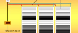
- To the heated floor system;
- To the heating element;
- To the heater.
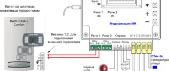
Connecting a thermostat to a heated floor system
A standard underfloor heating thermostat is supplied with detailed instructions for connecting the device to the underfloor heating system. You can connect the TP yourself using the markings under the terminal blocks.
Underfloor heating mat
On the back of the regulator there are three pairs of terminal sockets for wires. The first pair is intended for connecting a two-core network cable. Socket “L” – phase, “N” – zero.
The second pair of sockets is intended for connection to the underfloor heating terminals – L1 and N1. The fifth and sixth terminals are used to connect to the temperature sensor.
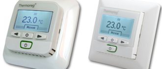
Connecting the thermostat
Floor temperature regulators can be inserted into a socket box or mounted on the wall. The temperature sensor can be either built into the body of the device or installed at the end of an external cable.
In the first case, the air temperature inside the room is measured. In the second option, the sensor measures the degree of heating of the final floor covering.
Connecting the thermostat to the heating element
The thermostat must be connected to the electric heater through a magnetic starter. This is due to the fact that the power of the regulator is far from comparable to the power of heating elements.
A magnetic starter (MP) is needed when the thermostat controls several heating devices at once. The MP is cut into the phase wire in parallel with the thermostat. Adjustment of the operating modes of the heaters is carried out by a thermostat, the supply current passes through the MP. This makes it possible to use a three-phase power supply, which allows the operation of high-power heating elements.
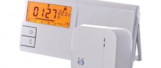
Many TRs are equipped with electronic microprocessors, which additionally provide indicators of the level of humidity, pressure and time required to achieve the values of the specified parameters.
Connecting the thermostat to the heater
Thermostats can be mechanical or electronic. Recently, the second models have been actively displacing their mechanical counterparts. The use of modern electronics makes it possible to more effectively control the temperature in a given environment.
TRs for room heaters are built into heater housings or placed away from heating devices. The regulator, first of all, is connected to the electrical network, then through the control circuit it is connected directly to the temperature sensor.
Additional Information. In most cases, infrared heaters are connected to a thermostat via a magnetic starter. To connect the device correctly, you must strictly follow the instructions provided.
Features of how temperature control devices are connected depend on the type of heating devices. This can be a single-core or two-core connection of TP underfloor heating. The connection of a two-phase thermostat to three-phase current heating elements is carried out only through a magnetic starter. For water heating, the thermostat is embedded directly into the radiator. Each specific case has its own thermostat connection diagram.
Electric boilers
A fairly common alternative to gas and solid fuel boilers. Lots of advantages, high efficiency, but long payback period. The connection is simple, like with gas boilers, but without a cold water supply. Temperature regulation and overheat protection are provided.
Mechanical boiler timer
Using a simple mechanical timer for an electric boiler, there are three options for starting the central heating system :
- The boiler is turned off;
- The boiler supplies warm water;
- The boiler turns on and off at the set time.
Mechanical timers usually have a large round dial with a 24-hour scale in the center. By turning the dial, you can set the desired time, and then leave it in that position. The boiler will turn on at the right time. The outer part consists of a set of tabs for a 15-minute period, which are inserted for easy adjustment of operation and mode settings. Emergency reconfiguration is possible, which is performed with the boiler connected to the network.
Mechanical timers are easy to set up, but the boiler always turns on and off at the same time every day, and this may not satisfy the owners if the family is large and bathing procedures are carried out several times a day at different times.