SNiP 3.05.01-85 ________________ Registered by Rosstandart as SP 73.13330.2011. — Note from the database manufacturer.
BUILDING REGULATIONS
INTERNAL SANITARY SYSTEMS
_____________________________________________________________________ Text Comparison of SNiP 3.05.01-85 with SP 73.13330.2012, see the link. — Note from the database manufacturer. _____________________________________________________________________
Date of introduction 1986-07-01
DEVELOPED by the State Design Institute Proektpromventiliya and the All-Union Scientific Research Institute of Hydromechanization, Sanitary-Technical and Special Construction Works (VNIIGS) of the USSR Ministry of Montazhspetsstroy (Candidate of Technical Sciences P.A. Ovchinnikov - topic leader; E.N. Zaretsky, L.G. Sukhanova, V.S. Nefedova; candidates of technical sciences A.G. Yashkul, G.S. Shkalikov).
INTRODUCED by the USSR Ministry of Montazhspetsstroy.
PREPARED FOR APPROVAL BY Glavtekhnormirovanie Gosstroy USSR (N.A. Shishov).
APPROVED by Decree of the USSR State Committee for Construction Affairs dated December 13, 1985 N 224.
With the entry into force of SNiP 3.05.01-85 “Internal sanitary systems”, SNiP III-28-75 “Sanitary equipment of buildings and structures” loses its force.
AMENDED Change No. 1, approved by Decree of the State Construction Committee of Russia No. 17 dated 02.24.00, put into effect on 07.01.00 and published in BLS No. 4, 2000.
The change was made by the database manufacturer according to the text of BLS N 4, 2000.
These rules apply to the installation of internal systems of cold and hot water supply, heating, sewerage, drains, ventilation, air conditioning (including pipelines to ventilation units), boiler rooms with steam pressure up to 0.07 MPa (0.7 kgf/sq.cm ) and water temperatures up to 388°K (115°C) during the construction and reconstruction of enterprises, buildings and structures, as well as for the manufacture of air ducts, assemblies and parts from pipes.
GENERAL PROVISIONS
1. GENERAL PROVISIONS
1.1. Installation of internal sanitary systems should be carried out in accordance with the requirements of these rules, SN 478-80, as well as SNiP 3.01.01-85, SNiP III-4-80, SNiP III-3-81, standards, technical specifications and plant instructions — equipment manufacturers.
When installing and manufacturing components and parts of heating systems and pipelines to ventilation units (hereinafter referred to as “heat supply”) with water temperatures above 388 K (115 ° C) and steam with a working pressure of more than 0.07 MPa (0.7 kgf/sq. cm) you should also follow the Rules for the Construction and Safe Operation of Steam and Hot Water Pipelines, approved by the USSR State Technical Supervision Authority.
1.2. Installation of internal sanitary systems and boiler rooms must be carried out using industrial methods from pipeline units, air ducts and equipment supplied complete in large blocks.
When installing coatings on industrial buildings from large blocks, ventilation and other sanitary systems should be installed in the blocks before installing them in the design position.
Installation of sanitary systems should be carried out when the object (occupancy) is ready for construction in the amount of:
for industrial buildings - the entire building with a volume of up to 5000 cubic meters and part of the building with a volume of over 5000 cubic meters, which, based on location, includes a separate production room, workshop, bay, etc. or a complex of devices (including internal drains, heating point, ventilation system, one or more air conditioners, etc.);
for residential and public buildings up to five floors - a separate building, one or several sections; over five floors - 5 floors of one or more sections.
1.3. Before installation of internal sanitary systems begins, the general contractor must complete the following work:
installation of interfloor ceilings, walls and partitions on which sanitary equipment will be installed;
construction of foundations or sites for the installation of boilers, water heaters, pumps, fans, air conditioners, smoke exhausters, air heaters and other sanitary equipment;
construction of building structures for ventilation chambers of supply systems;
installation of waterproofing in places where air conditioners, supply ventilation chambers, and wet filters are installed;
construction of trenches for sewerage outlets to the first wells and wells with trays from the building, as well as laying inputs for external communications of sanitary systems into the building;
installation of floors (or appropriate preparation) in places where heating devices are installed on stands and fans installed on spring vibration isolators, as well as “floating” bases for installing ventilation equipment;
arrangement of supports for installing roof fans, exhaust shafts and deflectors on building surfaces, as well as supports for pipelines laid in underground channels and technical undergrounds;
preparation of holes, grooves, niches and nests in foundations, walls, partitions, floors and coatings necessary for laying pipelines and air ducts;
drawing on the internal and external walls of all rooms auxiliary marks equal to the design marks of the finished floor plus 500 mm;
installation of window frames, and in residential and public buildings - window sill boards;
plastering (or cladding) the surfaces of walls and niches in places where sanitary and heating appliances are installed, pipelines and air ducts are laid, as well as plastering the surface of grooves for hidden installation of pipelines in external walls;
preparation of installation openings in walls and ceilings for the supply of large equipment and air ducts;
installation in accordance with the working documentation of embedded parts in building structures for fastening equipment, air ducts and pipelines;
PREPARATION WORK
2.1. The manufacture of pipeline components and parts from steel pipes should be carried out in accordance with technical specifications and standards. Manufacturing tolerances should not exceed the values specified in table. 1.
Document year: 2019
Type of document: Act
Download formats: DOC, PDF
Test reports are drawn up in the form of document forms in which the results of testing the performance of mechanisms and equipment are recorded.
In today's article, we will consider in detail the testing of pipeline systems, sewerage systems, stairs and stepladders, roof fencing and fire tests.
Examples of drafting acts can be downloaded for free at the end of the article.
Hydraulic testing report for the heating and water supply pipeline system
Checks of heating and plumbing systems are carried out:
- when introducing new engineering communications;
- when reconstructing an existing one;
- during a routine check of the functioning of the system.
The step-by-step inspection and its results are recorded in the test report. The system is tested for tightness and strength in two ways, one of which is the hydraulic method: testing by using water with increased load. This method is suitable for indoor and outdoor systems (at temperatures not lower than +5C). The second method is pneumatic.
Forms of acts for executive documentation
Heating, ventilation and air conditioning (HVAC)
Hidden work inspection report download doc format
General work log download doc format
Hydrostatic or manometric leak test report download doc format
Thermal test report of the central heating system for effect download doc format
Report on flushing (purging) of pipelines download doc format
Hydrostatic test report for low pressure boilers download doc format
Individual equipment testing report download doc format
Passport of the ventilation system (air conditioning system) download doc format
Equipment acceptance certificate after comprehensive testing download doc format
Certificate of inspection of sections of engineering and technical support networks download doc format
Water supply and sewerage (VK)
Test report for internal sewerage and drainage systems download doc format
Certificate of acceptance of the system and releases of internal sewerage download doc format
Report of hydrostatic or manometric testing of the water supply system download doc format
Report on flushing (purging) of pipelines download doc format
Certificate of technical inspection of the water metering unit download doc format
Individual equipment testing report download doc format
Act on washing and disinfection of pipelines (structures) download doc format
Acceptance certificate for internal cold and hot water supply systems download doc format
Test report for water loss of internal fire-fighting water supply (option 1) download doc format
Test report for water loss of internal fire water supply system (option 2) download doc format
Certificate of inspection of sections of engineering and technical support networks download doc format
External water supply and sewerage networks (NVK)
Certificate of acceptance hydraulic testing of the pressure pipeline for strength and tightness download doc format
Certificate of acceptance hydraulic testing of a gravity pipeline for leaks download doc format
Act on washing and disinfection of pipelines (structures) download doc format
Report on flushing (purging) of pipelines download doc format
Certificate of acceptance hydraulic testing of a tank structure for water tightness (tightness) download doc format
Test report for water loss of external fire-fighting water supply system download doc format
Certificate of inspection of sections of engineering and technical support networks download doc format
Gas supply. Internal devices
Individual equipment testing report download doc format
Gas pipeline testing report for strength and tightness download doc format
Certificate for checking the welding technological properties of electrodes download doc format
Acceptance certificate for a gas distribution system facility completed by construction download doc format
Report on gas pipeline purge download doc format
Incoming inspection report for materials and equipment download doc format
Certificate of completion of installation work download doc format
Certificate on carrying out commissioning works of the main gas propulsion plant download doc format
Notice of the start of construction download doc format
Journal of anti-corrosion protection of welded joints SNiP 3.03.01-87 download doc format
Welding log of welded joints (STO Gazprom 2-2.2-136-2007) download doc format
Welding work log SNiP 3.03.01-87 download doc format
General work log download doc format
Construction passport of in-house (in-shop) gas equipment download doc format
Certificate for the installation of brackets and supports when performing work on the installation of an internal gas pipeline download doc format
Construction passport for hydraulic fracturing download doc format
Construction passport of the LPG tank installation download doc format
External gas pipelines
Individual equipment testing report download doc format
Gas pipeline testing report for strength and tightness download doc format
Certificate for checking the welding technological properties of electrodes download doc format
Acceptance certificate for a gas distribution system facility completed by construction download doc format
Report on gas pipeline purge download doc format
Incoming inspection report for materials and equipment download doc format
Certificate of completion of installation work download doc format
Certificate on carrying out commissioning works of the main gas propulsion plant download doc format
Notice of the start of construction download doc format
Journal of anti-corrosion protection of welded joints SNiP 3.03.01-87 download doc format
Welding log of welded joints (STO Gazprom 2-2.2-136-2007) download doc format
Welding work log SNiP 3.03.01-87 download doc format
General work log download doc format
Construction passport of underground (aboveground) gas pipeline, gas inlet download doc format
Certificate for the installation of brackets and supports when performing work on the installation of an internal gas pipeline download doc format
Construction passport for hydraulic fracturing download doc format
Construction passport of the LPG tank installation download doc format
Thermomechanical solutions for boiler houses
Certificate of readiness of the foundation (supporting structures) for installation download doc format
Certificate of inspection of equipment installation on the foundation download doc format
Report of internal and external inspection of the boiler before installation download doc format
Hydraulic test report for hot water boilers download doc format
Report of hydrostatic or manometric testing of a pipeline for leaks download doc format
Report on flushing (purging) of pipelines download doc format
Certificate for checking the welding technological properties of electrodes download doc format
Individual equipment testing report download doc format
Certificate of completion of installation work download doc format
General work log download doc format
Welding work log SNiP 3.03.01-87 download doc format
Journal of anti-corrosion protection of welded joints SNiP 3.03.01-87 download doc format
Process equipment and process pipelines
Journal of radiographic control VSN 478-86 download doc format
Journal of heat treatment of welded joints VSN 478-86 download doc format
Journal of welding work VSN 478-86 download doc format
Journal of ultrasonic testing VSN 478-86 download doc format
Journal of accounting and quality control of control (trial) welded joints VSN 478-86 download doc format
Quality log of welding materials and shielding gases for welding process pipelines download doc format
Journal of color flaw detection VSN 478-86 download doc format
Hydraulic test report for assembly units download doc format
Valve testing report download doc format
Pipeline testing report download doc format
Report on identified equipment defects OS-16 download doc format
Report on identified defects in M-27 equipment download doc format
Equipment acceptance certificate after individual testing download doc format
Acceptance certificate - transfer of equipment for installation OS-15 download xls format
Act on removing seals from equipment VSN 478-86 download doc format
The act of transferring working documentation for the execution of work download doc format
Acceptance certificate - transfer of equipment for installation download doc format
Conclusion on compliance with VSN 478-86 download doc format
Conclusion on checking the quality of welded joints of pipelines using the ultrasonic method VSN 478-86 download doc format
Conclusion on color flaw detection VSN 478-86 download doc format
Application for mechanical testing of samples of welded joints VSN 478-86 download doc format
Application for radiographic quality control of welded joints VSN 478-86 download doc format
Inventory of production documentation for installation of process pipelines VSN 478-86 download doc format
Inventory of production documentation for installation of technological equipment VSN 478-86 download doc format
Passport for assembly units of steel pipelines of complete pipeline lines VSN 478-86 download doc format
List of fittings included in the assembly units of steel pipelines VSN 478-86 download doc format
Protocol for cutting production welded joints VSN 478-86 download doc format
Protocol of metallographic studies of samples of welded joints VSN 478-86 download doc format
Verification protocol by external inspection and measurement of dimensions of welded joints VSN 478-86 download doc format
Register of production documentation for installation of process equipment and pipelines VSN 478-86 download doc format
Information on welded joints VSN 478-86 download doc format
Information about pipes and pipeline parts VSN 478-86 download doc format
Specification VSN 478-86 download doc format
List of flaw detectors for quality control of welded joints of pipelines VSN 478-86 download doc format
List of welders and thermal operators VSN 478-86 download doc format
Report on identified equipment defects OS-16 download doc format
mavego.ru
Certificate of pneumatic testing of pipelines
Pneumatic method: diagnosis by pumping the system with high pressure air. Often the method is used for external systems if the temperature on the thermometer is less than +5 Celsius.
The procedure for crimping pipes by pneumatic testing is given in the same SanPiN; the test report is drawn up in the required form, which is given in Appendix No. 3.
Requirements for drawing up test documentation:
- Filling in the name of the city and the date of compilation.
- Indication of the members of the commission (as in the hydraulic test, three parties are involved).
- Description of the pipeline: length, diameter, material of pipes and joints.
- Information about the pressure value: calculated value, to what value the pressure in the pipes was increased, final pressure, amount of reduction. The crimping time is indicated.
- In the “Decision of the Commission” section, each of its members signs with a transcript if the pipeline has passed pneumatic diagnostics and is sealed and durable.
The essence and types of crimping
Nowadays heating is most often carried out by a “water circuit” system. At the same time, heated water circulates through the works, imparting its thermal energy to the premises. Leaks are unacceptable; the pipeline must be completely sealed for normal operation. Pressure testing specifically creates a larger volume in the pipe than normal.
When this is done using air, it is called pneumatic pressing.
When using water, then hydropressing. The latter method is considered safer and therefore more popular. For this reason, an example of hydropressing is provided as a form.
When testing, it is recommended not to exceed the pressure inside the pipe more than 15 MPa. If we are talking about raising pressure with water, then there are limitations. The maximum possible pressure should not exceed the normal operating pressure by more than 30%.
Certificate of testing of external and internal sewerage for spillage
A test report for internal and external sewerage is drawn up as a result of checking the operability of the system. It confirms the position of the commission that the system has withstood the test of a spill of water, and the design complies with the design documentation, GOSTs and standards.
Diagnostics of the normal functionality of the sewer system is necessary when installing a new facility or after carrying out repair work on an existing system. Information about the performance check is entered into the report. The form is drawn up in the form specified in Appendix “D” to the Code of Rules 73.13330.2012.
The act specifies:
- name of the system and the facility in which it is installed;
- information about the members of the commission. Representatives of three organizations are needed: the general contractor, the customer and the installation company;
- information about the name of the project is written down;
- the results are entered: the number of simultaneously connected devices, as well as the connection time or filling of water on the floor (unnecessary ones are crossed out);
- the third paragraph states that no leaks were detected at the joints and through the walls. This means the system is suitable for use.
The decision is signed by the members of the commission.
What is pressure testing of a heating system - test goals. Press!
To put a heat supply or water supply system into operation, after all the necessary installation work has been carried out, it is necessary to test the finished structure.
At this stage, hydraulic tests are carried out, based on the results of which a certificate is drawn up indicating the suitability of the system for its intended use and its ability to withstand hydraulic shocks.
Purpose of testing
Carrying out hydraulic tests is not a whim or a whim.
Tests must be carried out after the creation of a new network or after major repairs, preventive maintenance and reconstruction of an existing one, and also before the start of the heating season.
After which new testing is carried out, and this continues until results that correspond to the norm are obtained. Actually, there are two stages of testing: preliminary and final.
Please note: pressure testing is carried out to check tightness and integrity, as well as to detect possible defects in any section of the water supply system, including boilers.
Such checks are the most popular pressure testing process for heating systems. This happens by simulating water hammer, when pressure is pumped into the system several times higher than the standard one.
Specialist's note: all defects and deficiencies discovered during the pressure testing must be eliminated immediately and without delay.
All rules for conducting inspections of this nature are always strictly regulated.
For hydraulic tests, regulatory documents are used. These are two SNiPs: 41-01-2003 and 3.05.01-85, as well as “Rules for the technical operation of thermal power plants” from 2003.
The test procedure is quite transparent and understandable:
Important test details
Actually, the act of conducting hydraulic tests becomes evidence of the tests performed.
In this case, the checks themselves can be carried out in one of two ways:
- manometric;
- hydrostatic.
The first testing method involves the use of pressure gauges that record and demonstrate the pressure in the system.
Please note: using pressure gauges, the amount of excess pressure is determined, which allows us to draw a conclusion about the reliability of the test.
The second method checks the real readiness of the system for operation by checking its performance at a pressure 50% higher than the standard. Any test lasts at least 10 minutes, the permissible pressure drop during pressure testing is no more than 0.02 MPa.
Good to know: the main document evidencing the conduct of tests is the corresponding act.
Such an act must be drawn up in the form and signed by all responsible persons.
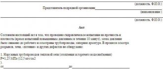
This document is extremely important; it must be filled out and signed on the same day as the inspection. A sample form is given in SNiP 3.05.01-85.
(You can download the heating system testing report form here).
There are also a number of strict requirements for the design and structure of this document:
- the act must indicate the date of the test and the drawing up of the document;
- all responsible persons for carrying out pressure testing must be listed;
- It is mandatory to indicate the full name of the object of inspection and the address where it is located;
- it is necessary to specify the test parameters, the location of the system check;
- bringing pressure indicators during tests: working, test and pressure at the end of tests;
- indicators of pressure drop in the system during the pressure testing process;
- results of inspection of structures and main components;
- a list of repairs carried out, if any;
- the fact of acceptance and a complete conclusion about the readiness of the system for operation;
- signatures of all authorized persons.
Certain points may vary somewhat depending on the nature and complexity of the object on which the tests were carried out and the reasons for their conduct.
Watch the video that explains the stages of pressure testing the heating system:
- Author: DmitriiG
heat.guru
Fire test reports
During testing for the performance and safe operation of fire equipment, several reports are drawn up:
- checking fire hydrants;
- diagnostics of internal water supply;
- checking for the safety of use and compliance with labor protection rules of fire escapes.
Fire hydrants
Testing the performance of hydrants for water loss is carried out twice a year and is often combined with checking the fire-fighting water supply system. Based on the results of the inspection, an act is drawn up and signed by the commission. Mandatory members: a representative of the fire inspection and a representative from the organization in which the inspection is taking place. Also, the commission may consist entirely of company employees.
The act states:
- general organizational information (information about the company, date and place of compilation);
- the main part describes the members of the commission and the progress of the test. Information about hydrants is presented in tabular form. The location address, diameter, pressure, water yield and affiliation of the hydrant are indicated;
- in the final part, compliance (or non-compliance) with the requirements of the hydrant condition is established.
At the end, the act is signed by authorized members of the commission.
Internal fire water supply
The act establishes the presence or absence of defects and malfunctions in the fire water supply system. The inspection is carried out by responsible employees of the enterprise. Frequency – at least twice a year; for flammable industries, inspections may be scheduled more often.
Internal fire water supply (IFP) is a complex system of pipes, sensors, and switches. Therefore, it is often checked by a labor protection or fire safety specialist, as well as by persons who are trained in fire safety.
The act is drawn up on letterhead or plain paper indicating the details. Be sure to register:
- information about the organization and participants of the inspection;
- information about the object being checked;
- inspection results;
- recommendations for eliminating defects and malfunctions, if any are found;
- signatures of responsible persons.
Roof fencing test report
Technical requirements and roof testing methods are enshrined in the same GOST as the standard for fire escapes and stepladders (53254-2009).
Tests are carried out at intervals of five years, integrity checks are carried out every year. The results are documented in acts.
The conditionally completed act can be divided into three parts:
- General information. Information about the tested object and the inspecting organization is entered here.
- Information about the inspection (what manipulations were carried out, what tools were used).
- Test results (compliance with GOSTs, integrity and safety of the structure).
The agreement of the commission members during testing is confirmed by their personal signatures.
Organizations with a license from the Ministry of Emergency Situations have the right to conduct inspections and tests. Defects found must be corrected.
Test report for ladders, racks and stepladders
Inspection and testing of racks, ladders and stepladders is carried out at least once every six or twelve months (depending on the object being tested and the material from which it is made).
Tests and checks for safe operation can be carried out by specialized organizations from outside or a commission specially created at the enterprise. At the same time, its members must be trained; an occupational safety or fire safety engineer is usually appointed as the chairman of the commission.
As a result of the diagnosis, the commission draws up a report; it is better to document it with the date of the inspection. The header indicates the name of the document, date and place of compilation. It is also important to indicate the details of the organization, list the members of the commission: their positions and full names.
In the main part, describe the tests of stepladders, ladders and racks:
- how many were checked, their inventory numbers, belonging to the workshop and department;
- what load was used and for how long;
- presence and absence of defects;
- availability of an assigned inventory number.
As a result of the test, suitability (or unsuitability) for use is established: they are safe, can withstand the required load, do not have defects in connections and fastenings, do not have sharp edges or burrs.
The signing of the act by the commission members indicates agreement with the results of the inspection.
By the way! If after this article you still have questions about how to fill out the forms, contact the site’s on-duty lawyer.
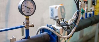
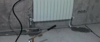
Installing the device in a heating system
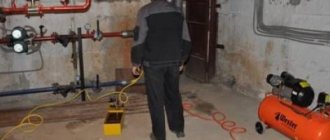
Pressure gauges are mounted using special three-way fittings. Thanks to them, devices can be changed and serviced without stopping the entire heating system. Moreover, taking into account the different pressure in each area, more than one pressure gauge can be installed inside a house (or apartment) equipped with a heating boiler. The presence of several instruments also simplifies pressure testing of pipelines, which is periodically carried out to monitor the reliability of heating.
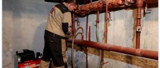
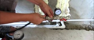
The process of installing a pressure gauge is not particularly difficult for most people - the work does not require any special experience or specialized tools. To install the device on a specially designed fitting, a regular plumbing kit is sufficient. However, if you choose the option of inserting a pressure gauge into the supply pipeline, installation will require a welding machine.
To protect the insulation from moisture, waterproofing and vapor barrier are used, which differ in their characteristics.
When using centralized heating, installation of the device is not the responsibility of the users - it is located as part of a waterworks unit, usually located in the basement of the building. The ideal place to place the pressure gauge is directly next to the boiler. It is not advisable to place other fittings between the device and the boiler (see How to install a solid fuel boiler, piping).